


 Chinese
 Spanish
 Russian
 Portuguese
 French
 German
 Indonesian
 Thai
 Vietnamese
 Arabic
 Italian
 Turkish
 Polish
 Japanese



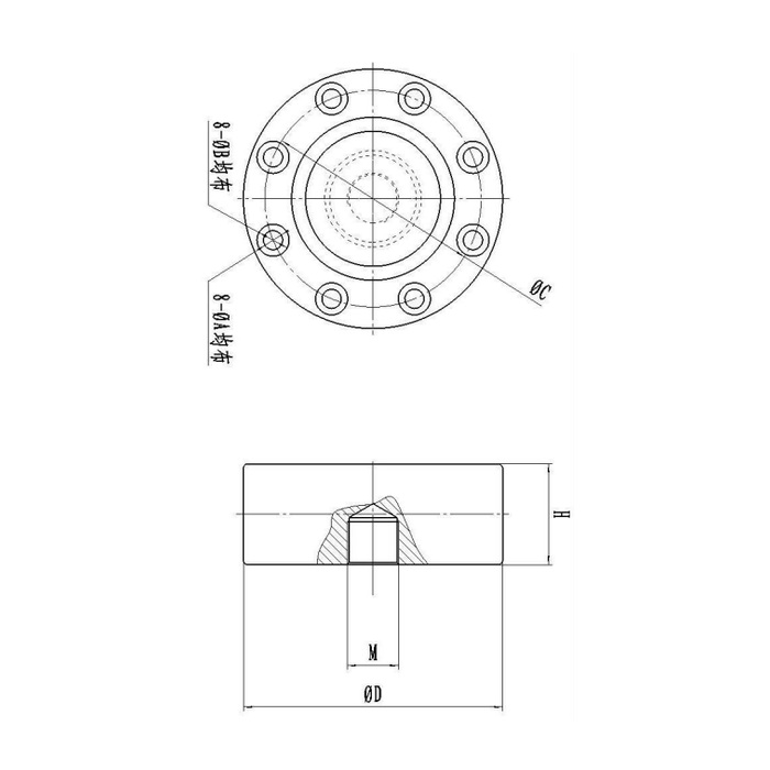
METRAVON MV-LC0033 is a spoke-type load cell with a 5-50 t technical reference. For an existing fixture, the useful question is which parts can safely remain: the base, centre adaptor, fixing bolts, reader and calibration record. The published outline and bridge entries overlap those of MV-LC0032. They do not document a verified performance advantage or a direct replacement relationship between the two model numbers.
Build a replacement record before removing the old spoke-type load cell
Record the nameplate, actual rated load, serial or calibration identity and the arrangement of the centre fitting and outer fixings. Measure the available space and photograph the surrounding support while the structure is safely secured. Obtain the old wiring functions and reader settings where possible. If the measured fault appears only after fitting a guard, connecting pipework or tightening an adaptor, investigate that external force path before deciding that a new sensing body will cure it.
Compare rated drawings instead of inferring a difference from the model suffix
The reference groups 5 and 10 t in a 105 mm-diameter, 34 mm-high body; the 50 t row is 141 mm in diameter and 51 mm high. Intermediate groups and fixing details must also match the selected rated unit. Request a marked comparison of the retained fixture against the offered drawing. Where two model references share the same visible outline, ask what delivered mechanical or electrical distinction applies to the quotation. A model suffix alone does not establish a different seal rating, precision or permitted load direction.
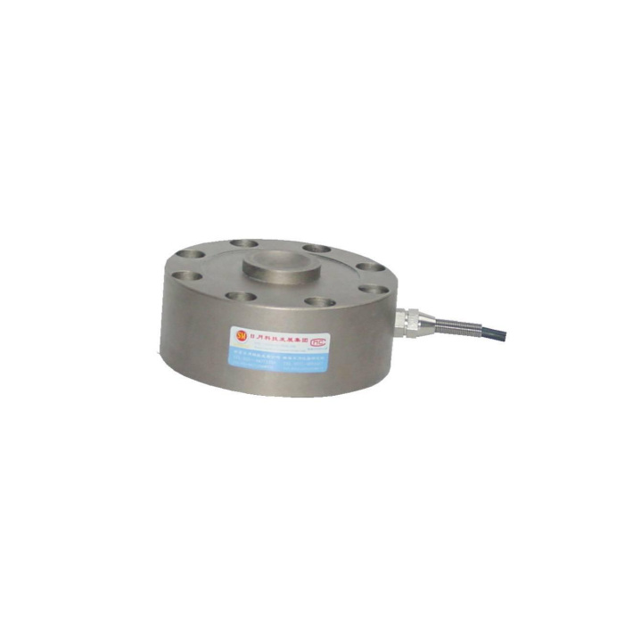
Keep the centre connection and base reaction as separate checks
Inspect thread form, engagement, shoulders and any contact damage on the old adaptor. Its ability to screw into a replacement does not establish a suitable bearing condition. Confirm the full thread specification for the offered rating; the smallest reference group lacks a complete thread entry. At the fixed perimeter, compare the hole and counterbore arrangement and the approved supporting surface. Retaining an old plate is appropriate only after those interfaces are agreed, not because its bolts can be inserted loosely.
Check the reader before copying the old calibration
This bridge is listed at 2.0 +/-0.015 mV/V with 10-12 V DC excitation, 780 +/-20 ohms input and 700 +/-5 ohms output resistance. Compare these values and delivered terminal functions with the existing channel. An old span setting may contain adjustments for a previous sensor or mechanical arrangement. After the new unit is assembled, establish zero and reference forces through the final adaptor. If the process needs tension and compression, require approval and calibration for both rather than treating a common sensitivity as evidence of bidirectional mechanical suitability.
| Item | Value | Selection notes |
|---|---|---|
| Old unit identification | Nameplate and calibration record | Match the actual offered version, not only the model family. |
| Retained mechanical parts | Base, adaptor and fixing section | Show contact surfaces and engagement, not just photographs. |
| Published technical interval | 5-50 t | A selected capacity requires its own dimensional comparison. |
| Rated bridge sensitivity | 2.0 +/-0.015 mV/V | Old span settings must be checked after mechanical assembly. |
| Input / output resistance | 780 +/-20 / 700 +/-5 ohms | Confirm the reader and junction arrangement if other cells remain. |
| Replacement acceptance | Reference loads and unloaded return | Record the final adaptor, restraints and reader settings together. |
Close the replacement with a traceable installed test
Agree loaded points that cover the useful operating interval, repeat them after unloading and record the final settings. Reference precision is 0.05% FS and temperature effect is 0.05% FS per 10 deg C; neither guarantees the error of the complete retained fixture. IP67 and the -40 to +85 deg C operating entry also need comparison with actual exposure. Separate sensor, adaptor and calibration items in the offer so a missing mechanical part does not appear only when production is stopped. No replacement approval follows from the 200% FS safe-load figure alone.
For the capacity-group dimensions used in an initial fixture layout, review the MV-LC0032 mounting discussion. Shared reference entries do not establish interchangeable supplied versions; the replacement still needs its own approved drawing.
Retained parts and replacement evidence
Q1. Is MV-LC0033 a higher-performance version of MV-LC0032?
No verified performance difference is established by their matching published entries. Ask the quotation to identify the offered version and any documented difference. The decision should follow the actual interfaces and required calibration, not an assumed hierarchy in the model number.
Q2. Can the old centre adaptor stay if it threads in by hand?
Thread engagement alone does not check shoulder contact, bottoming, wear or the permitted loading direction. Compare the complete adaptor section with the offered connection. Keep it only when the fit and force-transfer surfaces are approved.
Q3. What evidence shows that the replacement has solved the problem?
Record repeat readings and unloaded return through the final fixture under the operating conditions that caused the fault. A stable empty zero alone does not test loaded response. Retain the reference-force results and reader settings with the replacement identity.
