


 Chinese
 Spanish
 Russian
 Portuguese
 French
 German
 Indonesian
 Thai
 Vietnamese
 Arabic
 Italian
 Turkish
 Polish
 Japanese


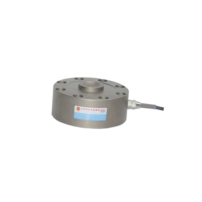

METRAVON MV-LC0032 is a spoke-type load cell for compact force fixtures and industrial weighing supports. The 5-50 t reference does not share one mounting envelope: diameter, height, hole size and centre connection change between rating groups. A fixture design should start with the selected rated outline and a section of the part that applies the force. A compact sensor body alone does not establish how a test adaptor or weighing support should bear on it.
Lay out the spoke-type load cell from the rated bolt circle
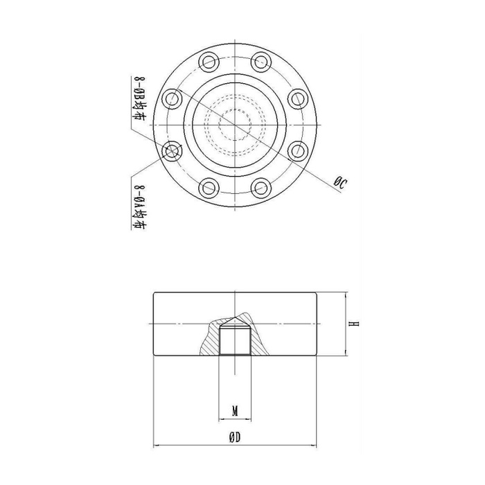
For 5 and 10 t, the metric table gives a 105 mm body diameter, 34 mm height and 90 mm bolt circle. At 20 and 30 t these become 121, 47 and 101 mm; the 50 t row gives 141, 51 and 119 mm. The outline shows eight fixing positions, with hole and counterbore sizes also changing by group. Do not issue a common adaptor plate for the whole capacity interval. Retain room for the side cable and gland as well as the round footprint.
| Item | Value | Selection notes |
|---|---|---|
| 5 / 10 t outline | 105 mm diameter / 34 mm height | 90 mm bolt circle; centre thread requires a complete definition. |
| 20 / 30 t outline | 121 mm diameter / 47 mm height | 101 mm bolt circle; centre thread entry 24 x 1.5. |
| 50 t outline | 141 mm diameter / 51 mm height | 119 mm bolt circle; centre thread entry 32 x 1.5. |
| Reference fixing arrangement | Eight positions | Use the rated hole, counterbore and supporting-face detail. |
| Input / output bridge resistance | 780 +/-20 / 700 +/-5 ohms | Check the excitation capability and signal input. |
| Precision / enclosure entry | 0.05% FS / IP67 | Installed fixture performance and exposure need separate acceptance. |
Specify the centre adaptor before assuming tension or compression suitability
The centre connection entry for 20 and 30 t is 24 x 1.5, while the 50 t row gives 32 x 1.5 under the thread heading. The 5 and 10 t row is not a complete usable thread designation. Request a rated connection detail with thread, engagement, bearing faces and load direction stated explicitly. General family references to tension/compression equipment are not approval for an arbitrary screwed adaptor, lifting attachment or reversed load. The eight outer fixings and the centre fitting have different jobs in transferring force.
Use a defined reaction surface rather than clamping every visible face
Show the base section, contact footprint and nearby guides to the supplier. A supporting plate must carry the intended reaction without introducing another path through a central stop, guard or surrounding frame. The reference description of stiffness and lateral-force resistance does not supply a permissible side-load number or fastener torque. Keep the force aligned with the approved fixture arrangement. If the sensor will be used in both directions, ask for the permitted mechanical build and calibration in each required direction before manufacture.
Match bridge electronics and useful force increments
Electrical output is 2.0 +/-0.015 mV/V at 10-12 V DC, with 780 +/-20 ohms input and 700 +/-5 ohms output resistance. A strain-gauge reader or suitable conditioner is required; the raw channel is not a PLC current-loop input. Reference precision is 0.05% FS. Define the useful force increments relative to the selected capacity and dead load of any adaptor. A higher range can accommodate more load but does not automatically preserve the same useful small-force discrimination in the assembled machine.
Accept the fixture with its production adaptor and cable restraint
Use agreed reference forces applied through the final centre fitting, then compare repeat loading and unloaded return. Investigate a reading change caused by tightening a guard or moving a cable before retaring it away. IP67 is the specified protection; provide actual water and cleaning exposure rather than assuming an immersion or high-pressure-wash allowance. The stated -40 to +85 deg C operating interval is separate from the 0.05% FS per 10 deg C temperature effect. Confirm material choice and safe handling of the fixture; the 200% FS sensor safe-load entry is not a validation of the adaptor.
Fixture plates, centre adaptors and tightening
Q1. Can one fixture plate cover all five listed ratings?
The reference changes body size, bolt circle and height between groups. Compare the selected rated drawings before deciding whether any adaptor can be shared. A plate that fits the 5 t pattern does not automatically accept the 50 t body.
Q2. Is the centre thread fully specified for a 5 t order?
The reference row does not give a complete thread designation. Request the actual offered connection, engagement and contact section. Do not choose a tap or adaptor from the larger-capacity thread entries.
Q3. Can the outer bolts be tightened to a standard torque chosen from hole size?
Hole size alone does not define bolt grade, thread engagement, supporting material or an approved tightening procedure. Obtain the mounting requirements for the selected sensor and fixture, then verify zero and response after assembly.
