


 Chinese
 Spanish
 Russian
 Portuguese
 French
 German
 Indonesian
 Thai
 Vietnamese
 Arabic
 Italian
 Turkish
 Polish
 Japanese



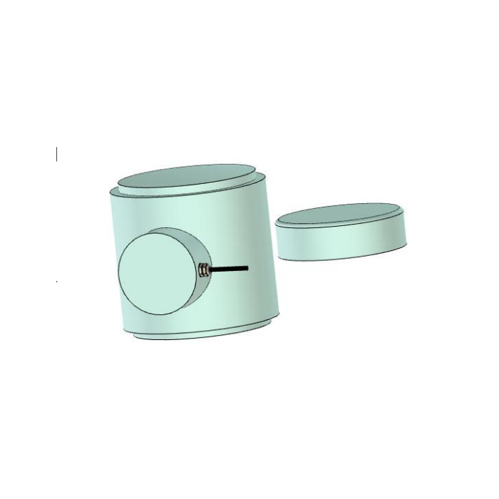
METRAVON MV-LC0031 is a compression column load cell for heavy weighing and force-support arrangements. The reference illustration shows a cylindrical sensing body and a separate bearing part. Its documented electrical sensitivity is 1.5 mV/V, which deserves attention when an existing weighing channel was configured for a different output. Before choosing a unit, request a confirmed rated force with its unit and a matching bearing-to-bearing assembly drawing.
Specify compression column load cell capacity in an unambiguous unit
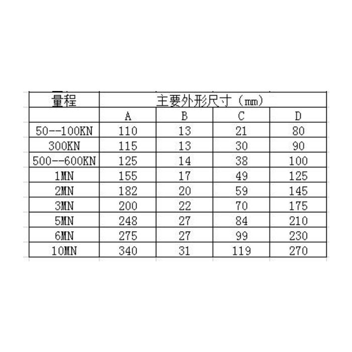
A force rating in kN or MN is not a mass rating in tonnes. Put the maximum applied compression, any significant external reactions and the required measurement interval on the enquiry, with explicit units. The outline and summary range entries do not establish one consistent continuous capacity range. Require a model-specific rating on the offer instead of copying the largest printed number into a purchase order. Any force-to-mass interpretation used by the project must state its basis.
Define the column, bearing parts and available support gap
Show the complete upper and lower load-transfer arrangement, not just the cylindrical body. Identify which bearing parts will be supplied and which existing parts must remain. The reference dimension letters and values need confirmation against a complete rated drawing before they are used for machining. Ask for the contact diameters, profiles and installed height with their datums marked. The self-centring description does not specify a permitted angle, horizontal travel or restraint strength. Guides and lift-off protection remain mechanical design requirements for the installation.
Check a 1.5 mV/V channel before reusing the old instrument settings
The bridge is specified at 1.5 +/-0.002 mV/V, with 10-12 V DC excitation, 750 +/-20 ohms input resistance and 700 +/-5 ohms output resistance. Confirm that the reader can supply and measure that bridge, especially if several supports are connected. Reusing a calibration intended for another sensitivity can give an incorrect force scale even when the unloaded display appears normal. Terminal functions should come from the delivered wiring record; the reference text and circuit disagree about signal-colour polarity.
| Item | Value | Selection notes |
|---|---|---|
| Required capacity definition | Force value plus kN or MN | Match the offered force rating to a confirmed rated drawing. |
| Rated electrical sensitivity | 1.5 +/-0.002 mV/V | Check the reader range and remove unsuitable old span settings. |
| Excitation | 10-12 V DC | This is bridge excitation, not a 24 V process-output supply. |
| Input / output resistance | 750 +/-20 / 700 +/-5 ohms | Include all connected supports in the channel review. |
| Precision / temperature effect | 0.3% FS / 0.03% FS per 10 deg C | These are different entries, not interchangeable accuracy claims. |
| Mechanical and enclosure definition | Rated drawing and selected protection | Confirm dimensions, bearing parts and actual exposure before order. |
Agree acceptance at the forces that matter to the process
The technical precision entry is 0.3% FS, with temperature effect stated separately as 0.03% FS per 10 deg C. Do not replace one with the other or apply either as a percentage of every small reading. State the loaded points, useful force increments and repeat cycles that will decide whether the installed system is acceptable. Check unloaded return with the final bearing parts and restraints in place. A claimed application in vehicle or rail weighing does not by itself establish a dynamic accuracy class, permissible operating speed or legal-for-trade approval.
Resolve sealing and structural limits before committing the assembly
The enclosure statements differ between the feature list and technical table, so the quotation must identify the supplied protection rating and its exposure conditions. Include water accumulation, cable termination, cleaning and corrosion in that confirmation. Operation is listed from -40 to +85 deg C; material options are alloy steel or stainless steel. The 200% FS safe-load entry is not a site proof-load procedure and does not approve the bearing parts or foundation. Keep those structural checks separate from sensor calibration.
Force units, calibration and moving supports
Q1. Can I order from a force number without stating the unit?
No. An enquiry must distinguish kN, MN and any mass quantity used by the project. Request the offered sensor rating in one explicit unit, together with the drawing for that rating. Do not infer an available capacity from an inconsistent range entry.
Q2. Will the old 2 mV/V setup give the right reading?
It cannot be assumed to do so. This reference specifies 1.5 mV/V. Check the reader input and excitation requirements, then calibrate the complete supported assembly with an appropriate reference method.
Q3. What needs confirmation if the support can move sideways?
Describe the movement and the forces to the assembly designer, with the seat sections and guides. The available self-centring description supplies no universal displacement or side-load allowance. Confirm that the bearing parts can operate as intended without the guides sharing the measured compression.
