


 Chinese
 Spanish
 Russian
 Portuguese
 French
 German
 Indonesian
 Thai
 Vietnamese
 Arabic
 Italian
 Turkish
 Polish
 Japanese


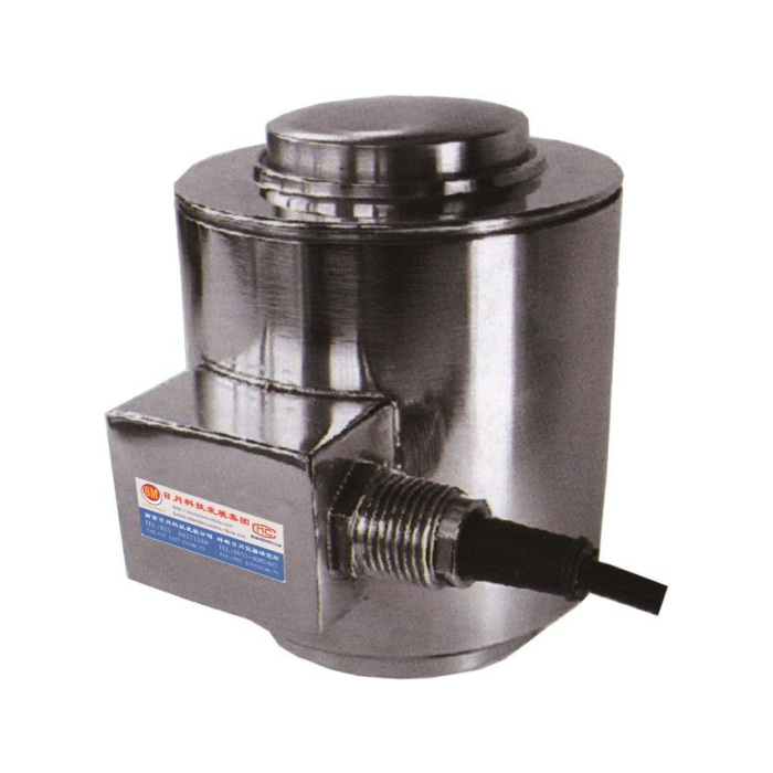

METRAVON MV-LC0030 is a compression column load cell for heavy supports with a curved upper contact and central base thread. Its reference range is 10-500 t. The installation decision needs more than a rated tonnage because the outline groups overlap at 50, 200 and 300 t. At those boundaries, request the exact offered mechanical version before choosing a seat, mounting pocket or base adaptor.
Identify the compression column load cell build at a range boundary
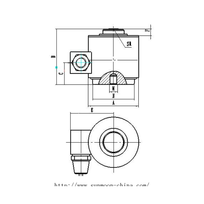
The metric outline groups are 10-20, 30-50, 50-200, 200-300 and 300-500 t. A 50 t requirement therefore appears in two different dimensional groups. The 30-50 group gives body A = 100.6 mm, overall B = 127 mm, SR = 152 mm and M18; the 50-200 group gives A = 150.6 mm, B = 184.5 mm, SR = 400 mm and M20. These are materially different mounting references. Specify which rated drawing and revision form part of the quotation rather than allowing the installer to choose a row from the capacity alone.
| Item | Value | Selection notes |
|---|---|---|
| Published outline groups | 10-20 / 30-50 / 50-200 / 200-300 / 300-500 t | The repeated boundaries need an explicitly selected drawing. |
| 30-50 t: A / B / SR / M | 100.6 / 127 / 152 mm / M18 | Do not assume this row applies to every 50 t quotation. |
| 50-200 t: A / B / SR / M | 150.6 / 184.5 / 400 mm / M20 | The other 50 t reference changes height, seat profile and base fixing. |
| 200-300 t: overall B / thread | 229 mm / M20 | Select the exact rated build at the 200 or 300 t boundary. |
| 300-500 t: overall B / SR | 215.9 / 1143 mm | B and SR describe different geometry; do not swap their roles. |
| Bridge input / output resistance | 400 +/-20 / 380 +/-5 ohms | Confirm reader loading and the delivered sensor configuration. |
Match the top contact and lower support as separate interfaces
SR labels the curved upper profile; it does not describe installed height or a permitted sideways displacement. At the base, the outline shows a central thread and a supporting land. Confirm the mating upper seat, base contact, thread pitch and engagement for the actual selected build. Do not suspend a load from the base simply because a thread is present. Where an old support is to remain, show its section so that a shoulder, fastener or pocket cannot make unintended contact with the sensing body.
Keep the side-enclosure references in their correct datums
The plan includes a lateral E reference running from the side feature toward the sensor axis, not a complete overall-width annotation. Add gland and cable access when defining the surrounding pocket. The C reference locates the side feature vertically; it should not be used as total sensor height. At the high end, the tabulated overall B values also do not increase uniformly from group to group. Use the confirmed outline directly, without interpolation or assuming that the highest-rated version must be the tallest one.
Check the existing scale channel and recalibrate the accepted assembly
Rated output is 2.0 +/-0.002 mV/V, with 400 +/-20 ohms input and 380 +/-5 ohms output resistance at 10-12 V DC. Provide the reader and junction configuration if this sensor joins other supports. The raw bridge does not itself supply RS485 or a 4-20 mA process signal. Use a specified weighing interface where required, and confirm delivered terminal functions rather than relying on conflicting signal-colour annotations. Recheck calibration through the final upper contact and lower base, including unloading return; do not transfer the previous span merely because the nominal sensitivity is unchanged.
State performance requirements at the project operating loads
Provide maximum local compression, vessel or platform tare and the small net changes that affect the process. The 0.05% FS precision entry and 0.02% FS per 10 deg C temperature effect need to be judged against those loads, not against the family range as a whole. Agree reference points and installation conditions before acceptance. IP68 exposure, alloy-steel or stainless-steel selection and the -40 to +85 deg C operating interval also need project-specific confirmation. A 200% FS sensor safe-load entry neither qualifies a locally made base adaptor nor supplies a proof-load test for the installed structure.
Overlapping ratings and retained contact parts
Q1. Which drawing should be used for a 50 t order?
Have the supplier identify the actual offered version. The 30-50 and 50-200 t groups differ in body size, height, curved profile and base thread. The purchase order should reference the selected drawing, not leave a choice between the two rows.
Q2. Can an existing M18 base fitting be retained?
Only if the offered rated build specifies that connection and the complete support section is compatible. Another outline at the same boundary capacity uses M20. Check both the lower bearing arrangement and upper seat instead of resolving the choice through thread size alone.
Q3. Does SR400 mean a 400 mm-high sensor?
No. SR belongs to the curved upper contact. Overall height is B in the reference drawing. Match the upper seat profile and assembled height as two different requirements.
Q4. What is needed for a replacement quotation at 200 or 300 t?
Supply the old outline or measured installation section, the retained upper seat and base fitting, maximum reaction and instrument configuration. Ask for the exact offered rated drawing because those capacities also sit at overlapping group boundaries. List any required seat or adaptor changes separately.
