


 Chinese
 Spanish
 Russian
 Portuguese
 French
 German
 Indonesian
 Thai
 Vietnamese
 Arabic
 Italian
 Turkish
 Polish
 Japanese


How to Select and Install an Ultrasonic Level Sensor: Range, Dead Zone, Wiring and Troubleshooting
An ultrasonic level sensor estimates the distance to a liquid surface by timing an acoustic echo through the air space. It is commonly used in atmospheric tanks, wastewater basins, pump wet wells and open channels. It avoids permanent probe immersion, but temperature, vapor, foam, dead zone and unwanted acoustic reflections can affect its readings.
Before choosing a model, calculate the longest sensor-to-liquid distance at minimum level and the shortest distance at maximum level. Tank depth alone is not a sufficient range specification.
Measurement principle and level conversion
The transducer sends an acoustic pulse toward the liquid and receives the echo. At sound speed v and round-trip time t, distance D = v × t / 2. If the sensor reference plane is E above the tank bottom, level h = E − D.
For example, a 5.0 m reference height and 2.0 m measured distance give a 3.0 m liquid level. Verify the model’s reference plane and whether it reports distance, level or elevation.
Check maximum range and blocking distance together
The lowest liquid level creates the greatest distance to the sensor; the highest level creates the smallest distance. Both extremes must fall inside the usable measuring window. A blocking distance is a physical near-field limitation and cannot be removed merely by editing the measuring range.
For example, with a 5 m tank and a sensor reference at 5.3 m above the bottom, the closest distance at full level is only 0.3 m. A candidate with a 0.35 m minimum measuring distance would not be suitable at that mounting position.
Beam angle, obstacles and mounting nozzles
An acoustic beam expands with distance. A first geometry estimate is W ≈ 2D × tan(θ/2), where W is footprint diameter, D is distance and θ is full beam angle. Real detection also depends on side lobes and surface reflections.
Keep the beam clear of filling streams, agitators, beams, well walls and pipes. A long or narrow nozzle can generate near echoes; check nozzle diameter, length and transducer position against the selected installation drawing.
Probe materials, temperature and process limitations
Non-contact does not mean the probe is isolated from corrosive vapor. Ordinary basins may suit compatible engineering plastics, but acid mist or chemical vapor requires verification of transducer, seal and housing compatibility by chemical composition, concentration and temperature.
Sound speed changes with air temperature and gas composition. A single temperature sensor may not compensate for pronounced thermal stratification. Heavy vapor, vacuum, persistent foam or a pressurized vessel demands a separate technology review; selecting a longer nominal range is not a universal cure.
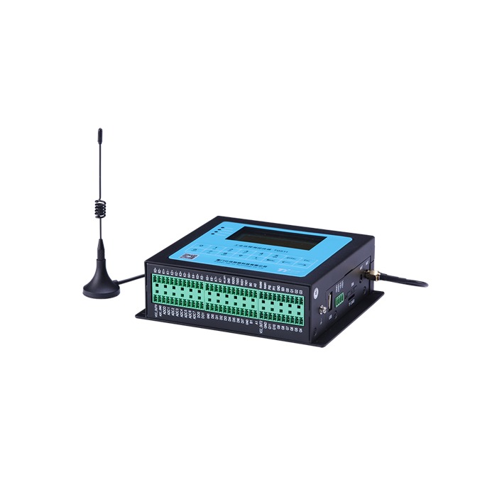
4–20mA and RS485/Modbus integration
A 4–20mA loop suits analog PLC inputs, provided wiring topology, available terminal voltage, load resistance and engineering-unit mapping are correct. With 4–20mA mapped to 0–5m of positive level, h = (I − 4)/16 × 5; 12mA corresponds to 2.5m. This formula does not apply to distance output or reverse mapping.
RS485 denotes the electrical interface while Modbus RTU denotes the protocol. Obtain the register map, address, baud rate, byte order and scaling before integration, and check bus topology, termination and signal reference.
Commissioning and maintenance checklist
- Confirm sensor datum, empty distance, extreme water levels and blocking distance
- Check acoustic beam coverage and suspected false echoes
- Compare independently checked level with local display and then PLC/RTU values
- Set reasonable filtering and loss-of-echo handling; do not smooth a wrong target into plausible data
- Inspect contamination, condensation, glands and mounting brackets
- Clean using the manufacturer’s approved procedure, and base inspection intervals on actual service history
Fast symptom-based troubleshooting
| Symptom | First checks |
|---|---|
| Echo loss at high level | Check minimum measuring distance |
| Jumps only during filling | Falling stream, splashing, agitation |
| Fixed offset | Datum, distance/level mode, PLC scaling |
| Error grows with temperature change | Compensation, stratification, gas composition |
| Local reading correct, platform wrong | Current mapping, registers, timestamp and units |
Information needed for a project quote
Provide the medium and concentration, vessel height and diameter, high/low levels, opening and nozzle dimensions, temperature and pressure, foam or vapor conditions, supply voltage, required 4–20mA or RS485 interface, cable length, quantity and destination. Site photographs often expose beam obstructions before equipment is ordered.
Frequently Asked Questions
Can ultrasonic level sensors measure wastewater?
Yes, provided foam, headspace conditions, splashing and transducer contamination are evaluated.
Can an ultrasonic sensor connect directly to a PLC?
Yes, if the PLC input matches the transmitter’s analog output or supported digital protocol.
When should radar be considered instead?
Evaluate a suitable radar or alternative technique when heavy vapor, pronounced stratification, vacuum or unavoidable acoustic obstacles dominate.
Worked Site Example: Check Range, Blocking Distance and Beam Clearance Together
Assume the sensor reference plane is 6.2m above the basin floor. Minimum and maximum liquid levels are 0.4m and 5.7m. The maximum sensor-to-liquid distance is 6.2−0.4=5.8m, while the minimum is 6.2−5.7=0.5m. The selected device must return a usable echo at 5.8m and have a specified minimum measuring distance below 0.5m with suitable allowance for level movement.
For a hypothetical full beam angle of 10°, the geometric footprint at 5.8m is approximately 2×5.8×tan(5°), or 1.02m in diameter. A pipe within 0.51m of the axis calls for a closer look at the manufacturer's beam diagram or a revised mounting position. This is a geometry estimate, not a hard acoustic boundary.
Field Acceptance Record
| Record | Site Evidence | Verification |
|---|---|---|
| Reference elevation | Measured installation datum | Compare with tank drawing |
| Independent level | Manual or trusted reference | Compare with local display |
| Analog/register value | mA or Modbus sample | Confirm span, direction and units |
| Dynamic conditions | Filling, pump stop, surface movement | Verify response and loss-of-echo behavior |
Request a Project-Specific Selection and Quote
Share the medium, high and low levels, mounting photographs or vessel drawings, power supply, required output, site conditions, destination country and expected quantity. Model suitability is assessed against the actual application rather than frequency, range or price alone.
METRAVON Radar Level Products | Send an inquiry | Arvin@metravon.com
