


 Chinese
 Spanish
 Russian
 Portuguese
 French
 German
 Indonesian
 Thai
 Vietnamese
 Arabic
 Italian
 Turkish
 Polish
 Japanese


Fire Water Tank Level Sensors: Technology Selection, Usable Water Volume and Low-Level Alarms
Fire-water storage tank monitoring supports the ongoing management of an emergency water supply. A project may need local level display, usable-water trends, low-level notification and reporting to a supervision system.
Before selecting a sensor, distinguish the physical water depth from the approved usable fire-water volume. A level reading alone cannot establish adequate fire-water storage, suction conditions or the suitability of independent protective functions.
Comparison of five measurement approaches
| Technology | Installation and strengths | Main limitations |
|---|---|---|
| Submersible hydrostatic | Immersed probe; economical for underground basins | Sediment, vented cable, density effects |
| Bottom pressure transmitter | Fixed connection through a reserved tapping | Requires sealing and isolation for service |
| Ultrasonic | Top-mounted non-contact option; economical at short range | Blind zone, temperature, walls, foam |
| Free-space radar | Top-mounted non-contact; independent of acoustic sound speed | Headroom, false echoes and cost |
| Magnetic level gauge | Can provide unpowered local indication | Bypass nozzles, float density and blockage risks |
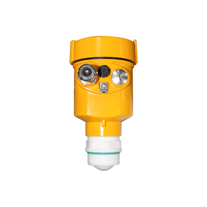
Choosing a method for underground fire-water tanks
For an existing underground basin with only a top access opening, a submersible hydrostatic probe may avoid the need for a new side-wall tapping. Position it away from bottom sediment and allow safe retrieval for service.
Where top clearance is adequate, radar or ultrasonic may be compared. Check high-level blocking distance and whether beams, inlets or walls enter the measuring footprint. Independently isolated compartments may show different levels; a single sensor must not automatically be assumed to represent all compartments.
Water level versus usable emergency volume
For a rectangular basin with constant cross-section, a first estimate of water above the approved minimum usable elevation is V = L × W × max(0, H − Hmin). Here L and W are usable length and width, H is current level and Hmin is the approved minimum usable level.
For an 8 m × 5 m tank at H = 2.5 m and Hmin = 0.5 m, the idealized result is 8 × 5 × 2 = 80 m³. Sloped floors, sumps, partitions and suction limitations require an approved level-volume table; this example is not a fire-storage compliance calculation.
Low-level alarms and fire-pump control
A continuous level signal can support monitoring, refill alerts and alarms approved by the fire-system design. High, low, low-low and device-fault states should be differentiated so communication loss is not misreported as a true low level.
Fire-pump start/stop behavior and safety interlocks must follow the applicable approved fire design. A general-purpose low-level alert must not be wired into an unauthorized pump stop function. Independent switches, redundant channels and certified components require project-specific engineering decisions.
4–20mA and remote monitoring integration
For a positive 0–4 m level mapping across 4–20mA, H = (I − 4)/16 × 4. A 12mA reading means 2 m of level. If the transmitter reports distance, reverse mapping or a different zero, use its actual configuration.
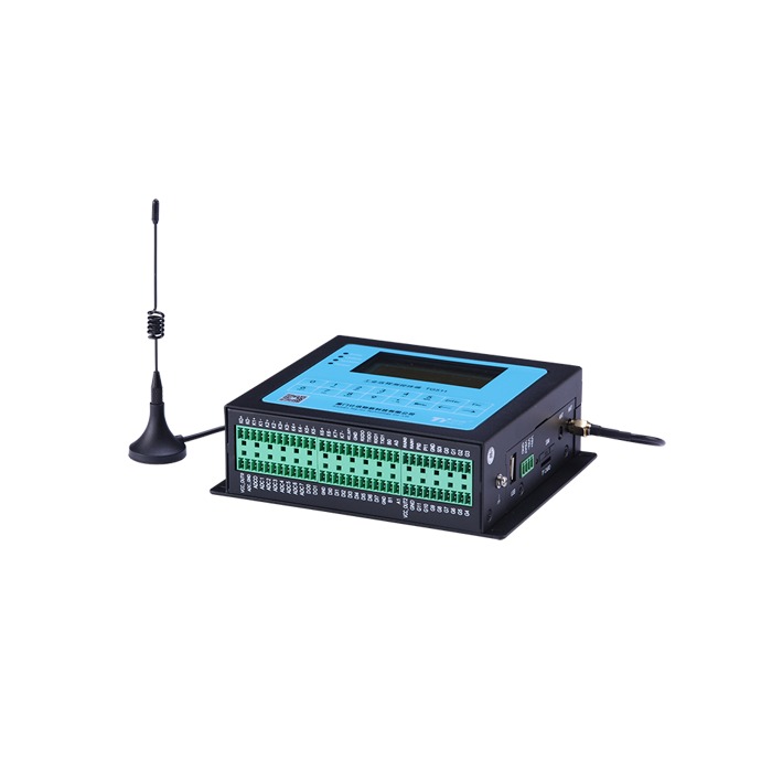
RS485/Modbus can support digital telemetry, but an ordinary industrial PLC, RTU or cloud platform is not automatically an approved fire alarm or pump controller merely because it reads level data. Fire-system interfaces must be validated against the approved design.
Installation, acceptance and routine verification
- Document the sensor datum, tank drawings and approved minimum usable level
- Check hydrostatic probe fixing, vent-tube moisture protection and sediment
- Check top-mounted clearance, beam obstructions and blocking distance
- Compare readings with an independent and reliable water-level reference
- Validate device faults, alarms and data displayed in the monitoring system
- Follow approved maintenance procedures without unauthorized bypasses
Data required for a fire-water tank inquiry
Provide underground/aboveground arrangement, tank dimensions, compartment count, access openings, suction and refill points, design high/low levels, approved alarm elevations, supply, output, quantity and country. List applicable fire-system standards and certification needs separately.
Frequently Asked Questions
Is radar mandatory for fire-water tanks?
No. Selection depends on the actual tank, applicable requirements and approved design.
Does one tank always need only one level sensor?
Not always. Independent compartments and separation of critical functions may require multiple points.
Commissioning Evidence and Compartmented Fire-Water Tanks
For a fire-water tank with multiple compartments, confirm the connecting arrangement and whether closing isolation valves can create different water levels. A single sensor must not be assumed to represent compartments that can operate independently. Measurement-point allocation must follow the approved design.
Acceptance evidence should include datum elevation, independent level reference, local and control-room values, approved low-level alarm thresholds, sensor-fault response and power-loss behavior. Alarm simulation should follow an approved procedure rather than deliberately depleting required emergency water storage.
Request a Project-Specific Selection and Quote
Share the medium, high and low levels, mounting photographs or vessel drawings, power supply, required output, site conditions, destination country and expected quantity. Model suitability is assessed against the actual application rather than frequency, range or price alone.
METRAVON Radar Level Products | Send an inquiry | Arvin@metravon.com
