


 Chinese
 Spanish
 Russian
 Portuguese
 French
 German
 Indonesian
 Thai
 Vietnamese
 Arabic
 Italian
 Turkish
 Polish
 Japanese


Hydrological Radar Water Level Sensors: River Applications, Installation and Maintenance
A hydrological radar water-level sensor is mounted above the water and uses electromagnetic echoes to measure distance. Typical deployments include rivers, reservoirs, bridges, canals, flood-prone roads and urban drainage. Non-contact operation avoids direct sediment exposure, but waves, floating objects and condensation on the antenna can still affect echo tracking.
The engineering priorities are a traceable elevation datum, a usable water target throughout seasonal extremes, and continuous trustworthy records.
Keep range, water depth and elevation distinct
For a radar reference-point elevation Zr and measured range D, water-surface elevation Zw = Zr − D. If Zr = 105.00 m and D = 8.20 m, Zw = 96.80 m. Water depth additionally requires an appropriate bed or local datum; it must not be inferred by subtracting an arbitrary constant.
FMCW radar estimates delay from beat frequency, while pulse radar may derive range from travel time. An incorrect installation elevation produces a fixed level-elevation error even when the range itself is correct.
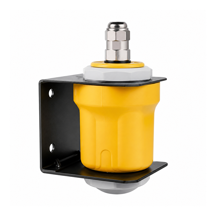
Selecting locations at rivers, bridges and reservoirs
Use both historical flood maxima and dry-season minima. High water determines near-field clearance; low water determines maximum range and whether the beam sees shallow banks or exposed bed.
Piers, railings, structural beams and gates may return strong echoes. A representative water surface across seasonal conditions is more valuable than simply increasing output damping.
Urban flooding and underground drainage
For underpasses, depressed roads and manholes, tie the measurement datum to the relevant hazard location such as the roadway low point or approved alarm elevation. One reading must not be presented as the deepest water across an entire underpass without validation.
Narrow wells require checks of blocking distance, walls, ladders, pipes and beam angle. Elevated humidity, corrosive gases and possible submergence impose additional housing and installation requirements.
Frequency, beam width and accuracy
Both 26 GHz and approximately 80 GHz instruments can serve hydrology. A compact 80 GHz antenna can more readily provide a narrow beam, but accuracy still depends on bandwidth, calibration, signal quality and site conditions; the band does not itself guarantee ±1 mm.
The footprint expands with measuring distance. Use the specific beam drawing and installation geometry rather than a universal rule such as installing exactly 0.5–1 m above flood level.
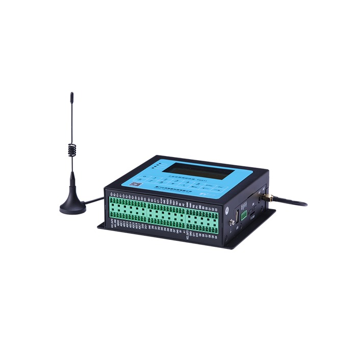
Telemetry, data timestamps and offline handling
The sensor provides distance or level, while an RTU or gateway handles logging, transmission and notifications. Define sample rate, upload interval, timestamps, alarm latency, heartbeat and stale-data indicators.
Offline backfill requires a logger with local buffering and later transmission. Records can continue during a network outage only while measurement and storage equipment remain powered; no new measurements are generally created while the station is fully unpowered.
Pre-season, during-flood and post-event maintenance
| Period | Priority checks |
|---|---|
| Before flood season | Datum, beam/antenna, bracket, power, communications, alarm tests |
| During flood | Data spikes, latency, loss of echo and power; avoid hazardous field access |
| After flood | Bracket movement, antenna contamination, debris, datum and reference comparison |
A disciplined troubleshooting sequence
Confirm actual water level first, then local display and raw range; next check echo quality and mounting, output signal and platform conversion.
For a fixed offset, start with datum and platform scaling. For dry-season spikes, inspect bank/bed echoes. For post-rain anomalies, inspect water film, glands and supply. If local readings are right but cloud readings are wrong, start with registers, scaling and timestamps.
A water-level sensor is not automatically a flowmeter
A conventional level radar does not directly report flow velocity or discharge. A stage-discharge relationship requires site-specific hydraulic validity; surface-velocity radar requires flow area and a calibrated conversion toward mean velocity.
RFQ information includes site drawings, extreme levels, elevation datum, river width and piers, supply and telemetry, data format, number of stations and acceptance criteria.
Frequently Asked Questions
Must radar be recalibrated after every flood?
Not automatically. Check the datum and instrument status first; verify or adjust only when evidence or project rules require it.
Is radar unaffected by rain, mist or floating debris?
No. Ordinary humidity is often less significant, but water films, ice and large floating targets can alter echoes.
Flood-Season Data Quality: Received Now Does Not Mean Measured Now
The telemetry system should preserve measurement time, server receipt time and device status separately. Backfilled records after a network outage must retain their original timestamps so that hours-old data are not presented as the current flood-warning level. Configure reasonable freshness limits, missing-data alarms and plausibility checks for physically unlikely rates of level change.
Before flood season, verify a traceable level datum and the full chain from local radar reading through RTU recording to platform trend and alarm. After major flood events, inspect mounting movement, bank changes and any new objects inside the beam footprint.
Request a Project-Specific Selection and Quote
Share the medium, high and low levels, mounting photographs or vessel drawings, power supply, required output, site conditions, destination country and expected quantity. Model suitability is assessed against the actual application rather than frequency, range or price alone.
METRAVON Radar Level Products | Send an inquiry | Arvin@metravon.com
