


 Chinese
 Spanish
 Russian
 Portuguese
 French
 German
 Indonesian
 Thai
 Vietnamese
 Arabic
 Italian
 Turkish
 Polish
 Japanese


Ultrasonic Level Commissioning and SAT: Blind Zone, Beam Clearance and 4–20 mA Verification
When an ultrasonic level instrument loses its target near a full tank, fluctuates or disagrees with the PLC, the cause may be beam geometry, near-zone blocking, gas correction, reference elevation or analog scaling—not necessarily a defective transducer.
Acceptance needs evidence from mounting, sensing, signal transmission and the PLC display. A correct local reading or a successful current simulation proves only part of that chain; record the limits of each test.
The acoustic beam has a footprint
Ultrasonic transducers radiate a diverging acoustic beam. Using a simplified cone and the vendor-defined full beam angle θ, the footprint diameter W can be estimated at distance D. Side lobes and effective boundaries vary by model.
W ≈ 2D × tan(θ/2)
Example: full angle 10°, distance 5 m gives W ≈ 0.875 m and radius ≈ 0.44 m.
If a wall, thermowell or inlet enters the footprint, evaluate whether an earlier false echo may dominate.
Do not impose one wall-clearance dimension on every meter. Use full-span geometry and the specific installation guide.
Maximum level must clear the blocking distance
Transducer ring-down and receiver recovery create a blocking distance near the sensor. Use the specified limit for the selected model and operating conditions, not a generic blind-zone dimension.
D_at_max_level ≥ B + M
B is the model-specified minimum distance and M is justified margin for installation tolerances and surface conditions.
Example: B = 0.30 m, top-of-range distance = 0.45 m gives 0.15 m geometric allowance; adequacy depends on duty.
Do not position a critical high-high alarm inside the blind zone and assume it will work. Use the approved safety design.
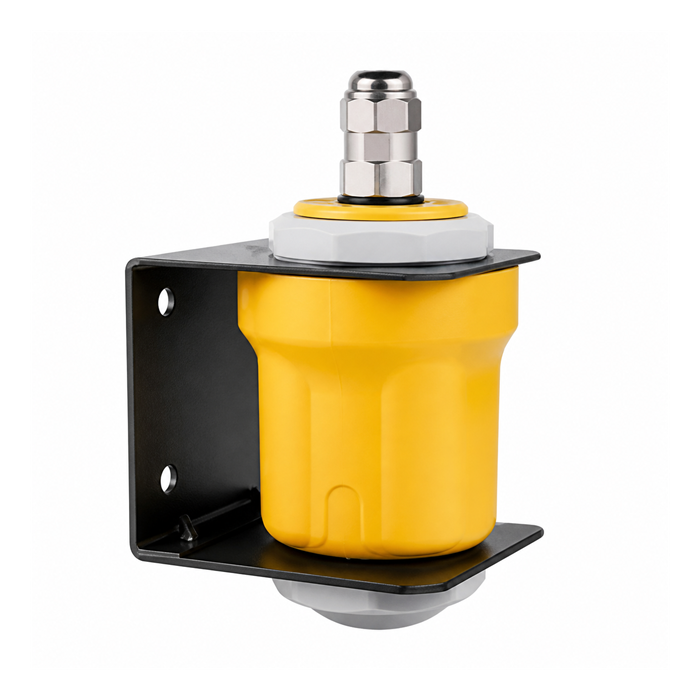
Nozzle geometry, aiming and gas conditions
Excessive nozzle length, narrow bore, steps and welds can cause close-range returns; verify the face position relative to the nozzle mouth.
Aim the transducer at representative liquid surface as specified, avoiding splash, filling streams and agitators.
Solid piles are sloped and irregular; there is no universal half-radius or two-thirds-radius mounting rule.
Hot vapor, strong temperature gradients or unusual gas composition can invalidate simple one-point correction; gas-path ultrasound cannot work through vacuum.
Condensation, oily buildup and ice on the sensing face can change returns.
Do not assume every ultrasonic model provides full echo graphs, false-echo mapping or keypad commissioning; confirm the manual.
Verify distance, level and 4–20 mA end to end
H = E − D
E is the probe-reference-to-zero distance, D measured surface distance.
Example: E = 6.00 m and D = 3.20 m give level H = 2.80 m.
H = H_low + (I−4)/16 × (H_high−H_low)
If 4 mA maps to 0 m and 20 mA to 5 m, 12 mA corresponds to 2.5 m.
A distance output or reversed span requires the corresponding map.
If local distance is correct but PLC level is wrong, inspect output variable, loop supply, input configuration, scaling and fault current before changing acoustic target-processing settings.

Site acceptance test and fault matrix
| SAT item | Acceptance evidence |
|---|---|
| Mount / beam | Transducer position, beam, nozzle dimensions and photos |
| Span / blocking | Highest and lowest levels within valid range |
| Datum | Check distance and level against independent references |
| Echo stability | Track target through representative conditions and accessible levels |
| Output / alarms | Verify analog/digital values, PLC map, fault state and approved alarm tests |
| As-built records | Save settings, wiring, reference points and signed results |
| Symptom | First check |
|---|---|
| Loss at full tank | Near-zone blocking, condensation, near-end obstruction |
| Permanent fixed value | Nozzle/internal false echo or stale held reading |
| Day/night bias | Gas correction, gradient and actual process variation |
| Jumps during filling | Splash, falling stream, acoustic blockage |
| PLC reading reversed | Confusion between distance and level or analog map direction |
If the acoustic conditions cannot be corrected, review another sensing method. METRAVON lists radar level transmitters; this is not a claim that a specific standard ultrasonic model is publicly available.
Commissioning FAQ
Q1. Must a tank be empty and full during commissioning?
Not necessarily. Use documented vessel geometry and the instrument reference point, then compare readings at safely available levels. Record which parts of the range were actually tested. Configuration or current simulation can verify scaling, but cannot prove echo tracking at an untested maximum fill level.
Q2. Will more damping correct installation error?
No. Damping can smooth valid readings, but cannot remove a nozzle obstruction, restore a target inside the blocking distance or correct a wrong reference height. Identify the cause first. After adjusting damping, test the response time needed by the control and alarm functions.
Q3. Can any ultrasonic meter handle dusty solids?
No. Confirm that the selected instrument is specified for the dust concentration, measuring distance, pile geometry and mounting arrangement. Test during filling as well as with settled material. A stable reading in a quiet silo does not establish performance through a filling dust cloud.
Q4. When should radar be evaluated?
Evaluate radar when the acoustic path is unreliable because of the gas conditions, persistent attenuation or unavoidable obstructions. Radar is not an automatic cure for foam or poor mounting. Compare the proposed model, antenna and nozzle arrangement against the actual process before changing technology.
Three commissioning case exercises
Case A: works at low fill, loses target near full
Measure the actual surface distance at maximum level and compare with the model blocking distance. Once inside the near zone, damping cannot restore valid measurement; review mount height or model.
Case B: local distance 3.20 m, PLC reports 3.20 m level
With reference-to-zero E = 6.00 m, actual level should be 2.80 m. Correct distance/level semantics, not echo processing.
Case C: stable by day, biased after sunset
Record true stage, transducer temperature, vertical gas gradients and condensation. Editing a fixed zero offset may worsen the other operating period.
Request engineering selection and quotation from METRAVON
Send tank dimensions, min/max levels, transducer height, beam angle and blocking distance, nozzle drawing, process gas conditions, controller interface and present symptoms. We can review the commissioning problem or alternative measurement technologies.
Engineering email: Arvin@metravon.com
Phone / WhatsApp / WeChat: +86 153 6781 2163
