


 Chinese
 Spanish
 Russian
 Portuguese
 French
 German
 Indonesian
 Thai
 Vietnamese
 Arabic
 Italian
 Turkish
 Polish
 Japanese


Tank-Farm Radar Level Retrofit: Nozzle Reuse, Loop Power and DCS Acceptance
Replacing radar level transmitters across a tank farm is a migration project, not a one-for-one hardware swap. An incompatible nozzle, an underpowered loop or an incorrect DCS range can derail a whole batch. A tag register, pilot installation, controlled cutover and site acceptance records keep the work traceable.
Before purchasing a replacement batch, establish which nozzles and circuits can be retained, which DCS points need reconfiguration and how existing protection will remain available during cutover. Radar distance accuracy alone does not establish custody-transfer accuracy.
One tank, one survey record
| Survey item | Reason |
|---|---|
| Tank ID, design and medium | Separate fixed/floating roofs, low-dielectric oils and chemical compatibility |
| Empty height, span, maximum fill | Verify near zone and farthest standoff |
| Flange, nozzle and antenna clearance | Check reuse and false-echo geometry |
| Original wiring and cable | Verify pairs, load, supply, barriers and shielding |
| DCS point and alarms | Verify distance/level semantics, scaling, fault output and safety layers |
Give every tank its own tag, photos, medium data, nozzle drawing and as-built configuration revision. Even nominally identical tanks may differ internally.
Nozzle reuse: matching flange size is not sufficient
Check flange DN/NPS, standard, pressure rating, facing and materials, plus nozzle bore and length, antenna position and internals. An adapter can solve bolt pattern mismatch while creating an excessive neck that causes near-field echoes.
- Survey existing openings first; never assume new drilling is permitted on a tank containing product or flammable vapors.
- Welding, cutting, pressure isolation, emptying and flange removal require approved change control and permits.
- Keep pilot echo traces in representative level states to check low-dielectric product and internal reflectors.
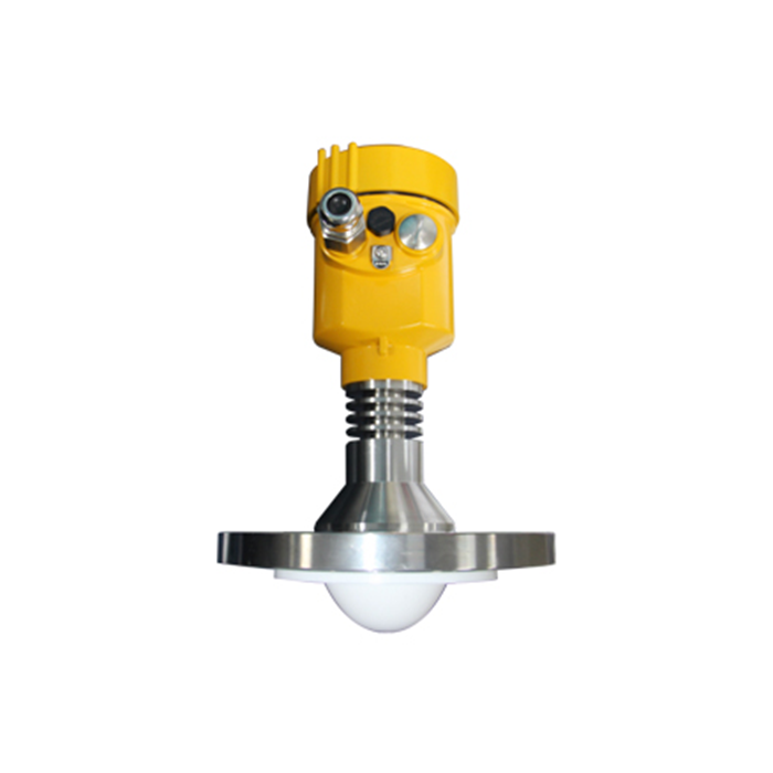
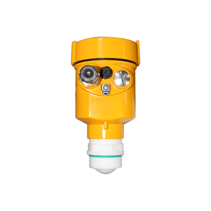
Use the METRAVON radar level category for potential antenna and connection choices, then validate against the exact datasheet.
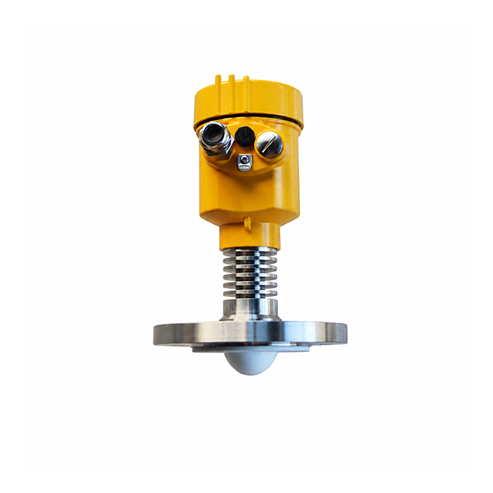
Two-wire and four-wire power budget
In a typical two-wire 4–20 mA loop, the same pair powers the device and carries analog output. Four-wire designs use independent supply and signal circuits. Two-wire does not automatically mean Ex ia; four-wire does not mean 220 V AC.
V_device = V_supply − V_barrier − I × R_series
R_series includes out-and-back cable resistance and relevant series input loads; V_barrier is the barrier/isolator drop under specified conditions.
Calculate with worst-case supply, allowed maximum output/fault current and the instrument minimum voltage.
HART also requires compatible loop impedance and interfaces. Intrinsically safe loops must meet certified entity parameters, wiring, earthing and protective requirements.
Cable reuse and DCS point migration
| Migration risk | Verification |
|---|---|
| Old two-pair allocation incompatible | Check actual supply/signal topology; rewire or select an appropriate model |
| Voltage drop or ageing insulation | Test conductors/insulation and worst-case supply |
| No free cabinet I/O | Assess expansion or appropriately rated remote I/O |
| Correct local value but reversed DCS | Check whether output is distance D or level H = E − D |
| Wrong analog map | Verify 4 mA, 20 mA engineering values and fault currents |
| Serial register problems | Verify address, byte order, data type, units and poll rate |
Clarify level versus ullage on the operator screen. Standardize unit, tank tag, fault state and last-update timestamp. Do not place an ordinary RTU in a hazardous zone without proper approval.
Keep overfill protection and custody-transfer duties distinct
Continuous process-level measurement is not the same as an independent high-high overfill protection layer. Do not remove an existing independent function merely because a new radar has been installed; assess requirements under the applicable risk framework.
Custody-transfer duties also require tank capacity tables, temperature, density, traceable calibration and applicable metrology standards. Millimetre-class sensor ranging alone cannot certify an entire tank gauging system.
Freeze the cause-and-effect and protection-function list before cutover; subject changes to approved MOC and testing.
Pilot installation, phased cutover and FAT/SAT
- Group tanks by geometry, medium, zoning and interface; prepare a tag register.
- Pilot representative tanks and prove mounting, echoes, loop power and DCS maps.
- FAT: verify configuration, certificate scope, factory parameters and I/O functions.
- Cut over tank by tank during approved work windows; do not bypass existing protection without authority.
- SAT: compare reference levels; verify representative ranges, faults, alarms, communication and records.
- Hand over as-built drawings, I/O list, parameter backups, healthy echo traces, test sheets and operator training.
Q1. Can an old flange be reused?
Only after checking the complete connection, not just the bolt pattern. Record flange standard, pressure rating, facing, seal material, nozzle bore and length, and the antenna position. An adapter must satisfy both mechanical requirements and the radar mounting limits; verify the echo after installation.
Q2. Can existing cable always be reused?
Reuse depends on conductor condition, circuit topology, shielding, area requirements and available voltage at the transmitter. Calculate the out-and-back voltage drop at the maximum specified current, including fault output. A cable that worked with the previous instrument is not evidence that the replacement loop has enough voltage margin.
Q3. How many tanks should be piloted?
Choose pilot tanks that represent the differences in the survey: medium, nozzle geometry, operating range, hazardous-area arrangement and DCS interface. A successful pilot on a simple water tank does not validate an oil tank with weak echoes or a different barrier. Define acceptance and rollback criteria before extending the rollout.
Q4. Can a new radar replace an independent high-high switch?
A process radar does not automatically replace an independent protection function. Retain the existing high-high protection unless an approved safety assessment and change process establish an acceptable alternative. Test the complete alarm or trip path before returning the tank to normal operation.
Operator handover and point-semantics control
Retain tank tags, state semantics and DCS engineering units unless an approved change requires otherwise. If the new instrument outputs distance D while the old system provided level H, a direct I/O swap without changing calculations can invert trends and alarm behaviour.
| Handover item | Define explicitly |
|---|---|
| Operator screen | Tank ID, level/ullage, alarms and last valid timestamp |
| Maintenance training | Lost echo, fault current, true/false targets and recovery |
| Configuration control | Factory defaults, as-built values, owner and revision |
| Parallel operation | Allowed differences, duration and retention of independent protection |
| Fault response | When readings are invalid, independent checks and escalation contacts |
Only use parallel monitoring when permitted by process safety and available connections. Do not bypass independent overfill protection or add unapproved nozzles for comparison.
Request engineering selection and quotation from METRAVON
Send tank counts, media and operating conditions, existing level-gauge models, nozzle drawings, cable and loop power data, DCS/PLC I/O list, hazardous-area classification and rollout timetable. We can review METRAVON radar options by tank group.
Engineering email: Arvin@metravon.com
Phone / WhatsApp / WeChat: +86 153 6781 2163
