Chinese
 Spanish
 Russian
 Portuguese
 French
 German
 Indonesian
 Thai
 Vietnamese
 Arabic
 Italian
 Turkish
 Polish
 Japanese

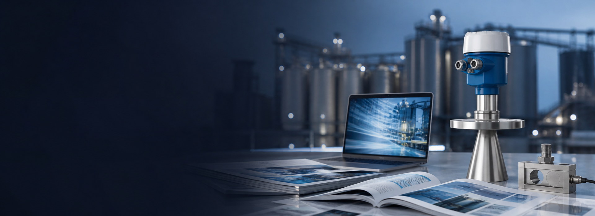
An uncorrected 25 °C air-temperature swing shifts the speed of sound by 15 m/s and adds 4.2-4.4 % distance error. Ultrasonic level transmitter temperature compensation corrects it by measuring air temperature and recalculating the speed in the time-of-flight conversion. It holds only while the probe reading represents the whole path; short indoor spans are easy, long outdoor spans usually need an external probe.
The sound-speed law behind ultrasonic level transmitter temperature compensation
An ultrasonic level transmitter fires a burst at the liquid surface and times the echo. Distance is d = c*t/2, where t is the round-trip time and c is the speed of sound in the gas between transducer and surface. The transmitter does not measure c; it assumes one. In dry air at 20 °C that value is 343.4 m/s, and the usual linear law is c = 331.4 + 0.6*T, with T in °C and c in m/s.
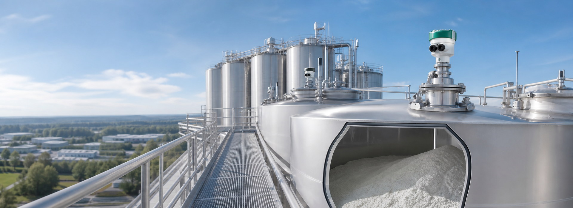
The consequence is a pure scale error. A 1 °C change alters c by 0.6 m/s, which is 0.17 % of 343.4 m/s, so a 6.000 m distance moves by about 10.5 mm per °C if nothing is corrected. Over a 25 °C day/night swing that is 262 mm, or 4.4 % of span. Ultrasonic level transmitter temperature compensation removes exactly this term: a temperature reading becomes a corrected c, and the time-of-flight result is recomputed. Nothing about echo quality, blind zone or surface condition improves; only the distance scale changes.
The worked distance error over a 25 °C swing
Worked example based on assumed site values (illustrative calculation, not field-measured data). A transmitter is calibrated at 20 °C, so it holds c = 343.4 m/s. The true distance is 6.000 m. If the air in the sound path is at 45 °C, the true speed is 331.4 + 0.6 * 45 = 358.4 m/s and the echo returns after t = 2 * 6.000 / 358.4 = 33.48 ms. The uncompensated transmitter computes d = 343.4 * 0.03348 / 2 = 5.749 m and understates distance by 0.251 m, or 4.2 %. The quoted 4.4 % is the linearised form 0.6 * 25 / 343.4 = 4.37 %; the exact value depends on direction, because the ratio inverts.
| Air temperature (°C) | c = 331.4 + 0.6T (m/s) | Echo time over 6.000 m (ms) | Indicated distance at fixed 343.4 m/s (m) | Error vs 6.000 m (mm) |
|---|---|---|---|---|
| -5 | 328.4 | 36.54 | 6.274 | +274 |
| 0 | 331.4 | 36.21 | 6.217 | +217 |
| 10 | 337.4 | 35.57 | 6.107 | +107 |
| 20 | 343.4 | 34.94 | 6.000 | 0 |
| 30 | 349.4 | 34.34 | 5.897 | -103 |
| 40 | 355.4 | 33.77 | 5.797 | -203 |
| 45 | 358.4 | 33.48 | 5.749 | -251 |
A 20 to 45 °C swing (25 °C) gives -251 mm; a -5 to 20 °C swing gives +274 mm; the 262 mm figure is the linearised 25 °C step taken at 20 °C.
These are calculated values for dry air at 1 bar, not product specifications. Confirm the compensated temperature range and the blind zone on the current data sheet; above roughly 40 °C the acoustic path and the transducer rating must be checked together.
The boundary condition is dry air of fixed composition at 1 bar and one uniform temperature along the whole 6.000 m path. Humidity, solvent vapor, carbon dioxide or a pressure change alter c in ways a temperature probe cannot see; where the gas is not ordinary air, the linear law itself is the wrong model.
Internal and external temperature probes
Most compact units carry an internal sensor bonded to the transducer or housing. It needs no extra wiring and tracks the electronics well, which is why ultrasonic level transmitter temperature compensation is usually enabled by default. The weakness is that the housing is not the sound path. A sunlit canopy can hold the housing 10 °C to 15 °C above the air in the tank, so the transmitter applies the wrong c to a cooler path.
An external probe in the vapor space, or a separate temperature transmitter wired into the level unit, measures the gas the pulse actually crosses. That is the better arrangement for outdoor tanks, open sumps and any long sound path. The trade-offs are an extra cable, a second point to maintain, and the need to keep the probe away from the wall, from direct sun and from the liquid surface.
- Internal probe: no extra wiring, follows housing temperature, drifts in direct sun.
- External probe: follows the sound path, needs a cable and a mounted position.
- Split units: confirm probe and processor share the same compensation coefficient.
- Compare the internal reading with an independent one at three heights; a difference above 2 °C makes one-point correction unreliable.

Residual error from a stratified sound path
A single probe measures one temperature while the pulse crosses a column that may be layered. On a clear morning the upper metre above a wastewater sump can be 5 °C warmer than the air near the surface, and a steam plume adds a different gas. If the path-average temperature differs from the probe reading by dT, the residual relative error is about 0.6*dT / c. For dT = 5 °C at 20 °C, that is 3.0 / 343.4 = 0.87 %, or 52 mm over the 6.000 m span, larger than the ±10 mm accuracy many sites expect from a compensated unit.
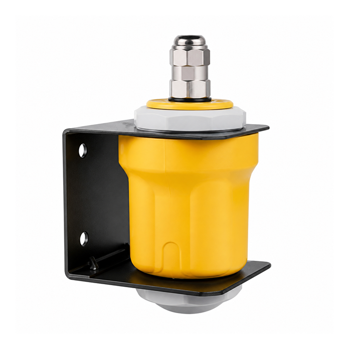
A stilling tube can flatten the gradient, but it brings conditions of its own: the bore must be smooth, the tube vented at the upper end so internal and external pressure equalise, and its lower end submerged below the lowest measured level. A tube that is too narrow or has a welded seam produces false echoes no temperature setting will fix. Ultrasonic level transmitter temperature compensation therefore has a definable limit: it corrects a uniform air temperature, not a gradient, a gas change or a vacuum. Where a 5 °C gradient is routine, add the residual to the error budget.
Radar as the escape route when compensation fails
Do not rely on an ultrasonic transmitter when the gas above the liquid is not ordinary air at near-atmospheric pressure. The method should not be used on sealed vessels whose pressure or vapor composition changes during the cycle, on vessels that can be evacuated, or where a persistent foam layer thicker than about 0.1 m covers the surface. In each case there is no single sound speed to compensate and the echo may be absorbed or scattered before it returns. A vacuum gives no propagation at all.
Switch to a radar level transmitter instead. Electromagnetic waves need no gas to carry them, and their travel time is unaffected by air temperature, humidity or moderate pressure changes. The change removes the entire 0.6 m/s per °C term from the error budget. Check the radar blocking distance on the current product page before ordering, because on a short span the near-field dead zone can replace the temperature error with a different limitation. A technical article on ultrasonic-to-radar retrofits covers preserving the existing mounting, cable and 4-20 mA input when the principle changes.
Commissioning evidence for the correction
Record the correction rather than assuming it is on. At handover, log the reference distance measured with a tape or fixed reflector, the indicated distance, the air temperature at the transducer and at a second point in the path, the enabled compensation mode and the coefficient in use. Repeat at the coldest and warmest part of the day; the two indicated distances should agree within the site error limit once the temperature term is applied. If they do not, look for a gradient, a composition change or a faulty probe before adjusting a span.
- Confirm the compensation coefficient in the configuration matches the calculation (0.6 or 0.607 m/s per °C; 0.607 comes from the fuller c = 331.3 * sqrt(1 + T/273.15) form).
- Verify the blind zone at the highest operating level, typically 0.25 m to 0.50 m depending on range.
- Check the 4-20 mA scaling and the datum after any change to the compensation setting.
- Keep the as-found and as-left readings with the date and the air temperature.
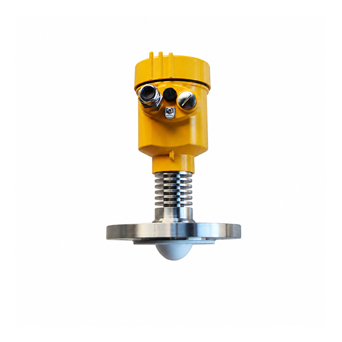
These records make ultrasonic level transmitter temperature compensation auditable. Without them a stable reading is indistinguishable from a correction that happens to be wrong in one direction.
FAQ
Q1. Is ultrasonic level transmitter temperature compensation always required?
Yes, on any vented tank whose air temperature moves more than a few degrees. Without it a 25 °C swing adds about 262 mm over 6.000 m, far beyond the ±10 mm most loops allow. Disable it only where gas temperature is constant, such as a climate-controlled indoor tank.
Q2. Can the compensation correct a reading that runs backwards?
No. A reversed output is a scaling or wiring problem. Temperature compensation changes only the c used in d = c*t/2; it cannot change the sign of the level or the 4-20 mA direction. Check empty distance, span and output direction first.
Q3. Which probe placement gives the better correction on an outdoor tank?
An external probe in the vapor space, shielded from sun and away from the wall, is the better choice. An internal sensor follows the housing, which can sit 10 °C to 15 °C above the sound path. Compare both at three heights; above 2 °C difference, one-point correction is unreliable.
Q4. How much error remains after compensation on a 6.000 m path with a 5 °C gradient?
About 52 mm, or 0.87 % of span, from 0.6 * 5 / 343.4. One probe cannot represent a layered air column. A stilling tube can flatten the gradient, but it must be smooth, vented at the upper end and submerged at the bottom. Add the residual to the error budget.
Q5. When should the instrument be replaced by a radar level transmitter?
When the gas phase is not ordinary air: sealed or evacuated vessels, changing vapor composition, solvent layers and foam above roughly 0.1 m. There is no single sound speed to compensate and the echo may be absorbed. Radar removes the temperature term, though its blocking distance must be checked.
Q6. What should the site acceptance record contain?
The reference and indicated distances, air temperature at the transducer and a second point, the enabled compensation mode, the coefficient, and the as-found and as-left readings with the date. Repeat at the coldest and warmest part of the day; keep both readings in the record.
SUMMARY
Ultrasonic level transmitter temperature compensation removes a predictable scale error: an uncorrected 25 °C shift moves a 6.000 m distance by about 262 mm, or 4.4 % of span, while c = 331.4 + 0.6*T reduces it to a few millimeters when one probe represents the path. A 5 °C layered path still leaves about 52 mm, so gradients, foam and vacuum remain outside the correction. The next step is to log the coefficient, probe position and a cold/warm pair of reference readings.
Talk to a METRAVON engineer about this application
Share the tank dimensions, the measured day and night air-temperature range, the gas above the liquid and the distance span. We will review whether a single temperature probe covers the whole sound path and whether the compensated range, blind zone and output scaling fit your site before confirming a configuration.