Chinese
 Spanish
 Russian
 Portuguese
 French
 German
 Indonesian
 Thai
 Vietnamese
 Arabic
 Italian
 Turkish
 Polish
 Japanese


Point level switch types fall into five families — tuning fork, capacitance, float, RF admittance and optical — and each has a different dominant failure mode — and two of them share the coating problem. A point level switch reports presence at one elevation, not a continuous value. Use it for high-high, low-low and pump protection on liquids and dry solids, paired with an independent continuous transmitter.
Grouping point level switch types by what they sense
A point level switch is chosen by the physical quantity that changes when the medium reaches the probe. A tuning fork senses damping of a vibrating tine; capacitance and RF admittance switches sense a change in electrical admittance between probe and vessel wall; a float senses buoyancy and moves a contact; an optical switch senses refraction at a prism tip. Grouping point level switch types this way explains why one product can trip a given design and be invisible to another.
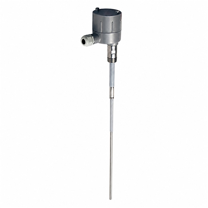
The output side is common to all five: a discrete state with a defined fail-safe direction. None reports how far above the probe the level has risen, so none replaces a continuous radar level transmitter for inventory or control. What a switch adds is a hard, independent boundary: a high-high unit mounted above the working band trips on rising level even if the transmitter, its 4-20 mA loop or the PLC scaling is wrong. That independence is lost the moment the switch shares a cable, an input card or a supply with the device it backs up.
Comparing failure modes across a single medium table
The table is a screening matrix, not a ranking. It gives a typical limiting condition for each family and the failure mode that most often produces a wrong state. A medium that violates the limiting condition rules the family out before price or wiring is discussed.
| Point level switch | Sensed variable | Min. dielectric er (-, 20 °C) | Min. bulk density (kg/m³, dry) | Max. viscosity (mPa·s, typical) | Dominant failure mode | Reset and fail-safe logic |
|---|---|---|---|---|---|---|
| Tuning fork | Vibration damping | not applicable | ~50 | ~10 000 | Tine bridging by coating gives a false wet state | Configurable; set de-energise-to-trip for high-high |
| Capacitance | Probe-to-wall capacitance | ≥ 2 | not applicable | not limiting | Coating or a product er shift gives a false high | Calibration-bound; re-verify after product change |
| Float | Buoyancy and travel | not applicable | not applicable | ~1 000 | Hang-up on sludge or crystallisation; contact wear | Mechanical; check electrical load before reuse |
| RF admittance | Admittance with driven guard | ≥ 1.5 | ~50 | ~10 000 | Conductive buildup defeats the guard and latches wet | Latching with manual reset for high-high |
| Optical | Refraction at prism | not applicable | not applicable | ~500 | Prism coating or crystallising liquid holds the wet state | Non-latching; prove dry state after cleaning |
These are typical engineering screening ranges, not product specifications. Confirm the dielectric constant, bulk density, viscosity and process temperature of the actual medium against the current data sheet and the delivered nameplate before ruling a family in or out.
The last two columns matter: a switch that resets while the tank is still overfilled has protected nothing. Point level switch types that can latch, such as RF admittance and configurable tuning forks, are usually preferred for high-high duty; a non-latching optical or float device suits pump protection where automatic restart is intended.
Ruling out a type by medium and coating behavior
Start eliminations with the medium. A liquid with a dielectric constant below about 2 cannot be trusted with a capacitance switch, because wet and dry states become too close to separate; the same family needs recalibration whenever the stored product changes. A float should not be used in liquids that crystallise, carry solids or exceed roughly 1 000 mPa·s, since the moving element can stick. An optical switch should not be specified for freezing or crystallising service, because a coated prism reports liquid that is no longer there. A tuning fork is unsuitable for very light dry powders below about 50 kg/m³, and heavy coating can bridge the tines into a permanent wet state.
This is where the method should be abandoned rather than tuned. If the medium coats every wetted part, or if its dielectric constant and bulk density both move with the batch, a single-point device cannot give a dependable state. Neither a sensitivity adjustment nor a longer delay changes the physics; RF admittance tolerates coating better than plain capacitance, but a conductive layer can still defeat the guard.
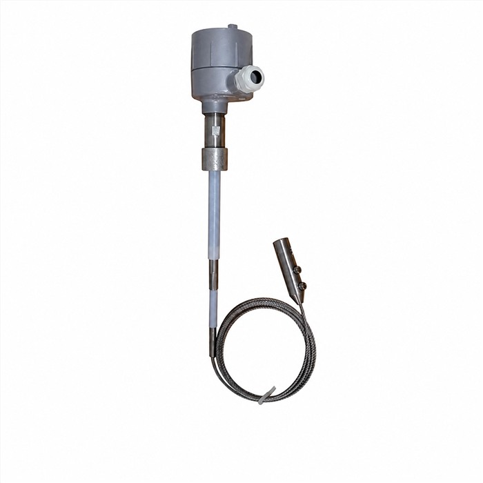
Setting the trip point from fill rate and shutdown delay
A switch at the right elevation still fails if liquid rises past it before the inlet closes. Worked example based on assumed site values (illustrative calculation, not field-measured data): a vessel with a 4.0 m² free surface receives 1.2 m³/min, so the rise rate is (1.2 / 60) / 4.0 = 0.005 m/s, or 5.0 mm/s. The shutdown chain adds 0.5 s of switch response, 0.3 s of controller scan and 3.0 s of valve stroke, a total of 3.8 s. During that delay the level rises 5.0 mm/s * 3.8 s = 19.0 mm.
- Add a margin for surface ripple and installation tolerance; doubling gives 38 mm.
- Round up and set the high-high trip at least 50 mm below the maximum allowable level. The 38 mm rounds up to 50 mm, leaving 12 mm for trip repeatability and installation tolerance.
- Recompute if the valve stroke is longer or the inflow rate increases.

The inflow used must be the maximum credible rate and the whole delay chain measured rather than taken from one data sheet. A test button on the switch exercises the electronics only; it does not prove the barrier, the PLC input or the valve. The proof test has to move the final element.
Keeping the alarm independent of the continuous transmitter
Independence is an electrical and physical property, not a label. The high-high switch should use a separate cable route, a separate PLC input, a separate barrier or isolator and, where practical, a separate supply from the radar level transmitter it protects. If both share an input card or a junction box, one fault removes the reading and the alarm together; a common 24 V DC supply with a single fuse is a frequent weak point.
Point level switch types also differ in how they report a fault. A two-wire NAMUR device can signal a broken line, while a simple relay contact cannot distinguish an open circuit from a dry tank unless the loop is supervised. Specify the fail-safe direction explicitly: for high-high duty the trip should occur when the loop is de-energised, so a cut cable produces an alarm rather than silence. The product page for each switch lists the load rating and available outputs; a technical article on alarm logic covers latching and proof-test intervals.
Checking mounting, load and proof-test details
For point level switch types, installation decides whether a correctly selected switch works. Align the tine faces with the flow and mount about 20° below horizontal where the design allows. Where the nozzle sits near a fill point, fit a baffle about 200 mm above the fork. On viscous media a vertical mounting reduces buildup. Cable entries should point downward, and the process seal must be rated for the full pressure and temperature, including vacuum.
- Match the contact rating to the actual load, including inrush, before reusing a float or relay output.
- Confirm the nozzle pocket gives the probe free travel and enough removal space.
- Verify the trip and reset band after cleaning, since a wet prism or coated tine may not clear.
- Record the as-found state, the test medium and the final element response.

The record should show the level, the switch state, the PLC input and the valve position together.
FAQ
Q1. Which point level switch types suit a coating, conductive liquid?
RF admittance with a driven guard is usually the first choice, because the guard reduces the effect of a coating layer. A tuning fork is the second option where viscosity stays moderate. Plain capacitance should be ruled out, since conductive buildup reads as a permanent wet state. Qualify the switch against more than one sample.
Q2. Can a point level switch replace the continuous radar level transmitter?
No. A point level switch reports one elevation only; it cannot provide the level value, trend or inventory that a radar level transmitter supplies. Use it as an independent high-high or low-low layer, not as the primary measurement. Keep separate cables, inputs and supplies so one fault cannot remove both.
Q3. How far below the maximum level should a high-high switch sit?
Derive it from the maximum fill rate and the measured shutdown delay. In the worked example, 5.0 mm/s over 3.8 s gives 19.0 mm; doubling for ripple and tolerance gives 38 mm, rounded to 50 mm. Use the maximum credible inflow and measure the whole chain from switch response to valve stroke.
Q4. Why does a capacitance switch trip after a product change?
Because its calibration is tied to the dielectric constant of the original liquid. A lower er moves the wet and dry states closer and the switch can miss the level; a higher er or a conductive coating can hold it wet. Re-verify after every product change, and rule the family out when er falls below about 2.
Q5. Should the high-high alarm latch or reset automatically?
Latch it, with a manual reset, for overfill protection. An automatic reset can clear the alarm while the tank is still above the trip point, removing protection before an operator confirms the state. Non-latching behavior suits pump low-low duty where automatic restart is intended. Verify both by lifting the wire at handover.
Q6. What does a proof test need to demonstrate?
That the whole chain works: medium reaching the probe, the switch changing state, the barrier and PLC input registering it, and the final element moving. Pressing a test button exercises only the electronics. Record the level, the switch state, the input status and the valve position with the test medium and date.
SUMMARY
Point level switch types are chosen by elimination: rule out a family when the medium violates its dielectric, density, viscosity or coating limit, then check reset logic and the electrical independence of the alarm. In the worked high-high example a 5.0 mm/s rise over a 3.8 s shutdown delay consumes 19.0 mm of headroom, so a 50 mm trip separation is the defensible minimum. The next step is to write the medium limits, trip elevation, fail-safe direction and proof-test scope into the loop drawing.
Talk to a METRAVON engineer about this application
Tell us the medium, its dielectric constant or bulk density, the viscosity, the process temperature and whether the alarm must latch. Our engineers will match a switch family to those conditions and check the trip elevation against your maximum fill rate and measured shutdown delay before recommending an output and mounting arrangement.