Chinese
 Spanish
 Russian
 Portuguese
 French
 German
 Indonesian
 Thai
 Vietnamese
 Arabic
 Italian
 Turkish
 Polish
 Japanese

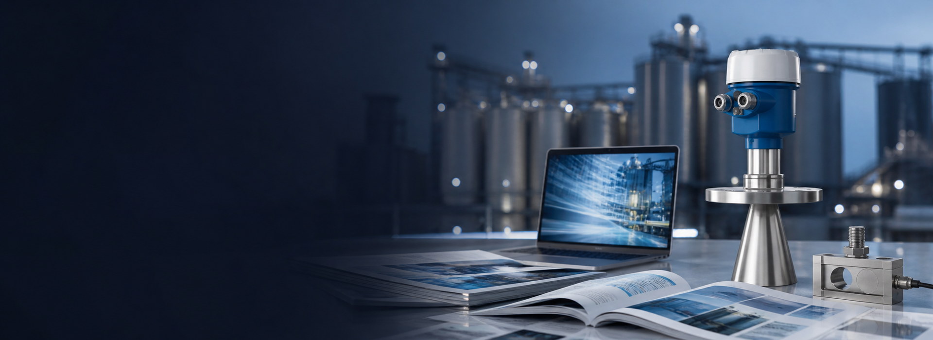
Level measurement in pressurized tanks is the continuous reading of the gas-liquid interface in a vessel held above atmospheric pressure, usually by a non-contact 80 GHz radar level transmitter. It covers LPG, liquid ammonia and liquid oxygen, where vapor permittivity, cryogenic materials and hazardous-area approval set the usable boundary. Typical spans are 0-12 m at up to 25 bar g.
Why level measurement in pressurized tanks needs vapor compensation
An FMCW radar level transmitter times a microwave sweep through the space above the liquid and computes distance as d = c*t/2. In dry air at 20 °C the relative permittivity is about 1.0006, so c sits within 0.03 % of its vacuum value. For level measurement in pressurized tanks the headspace is saturated vapor, not air, and the wave slows to c/sqrt(er). A transmitter still using the vacuum value overstates the distance by a factor of sqrt(er) - that is, by (sqrt(er) - 1) of the true distance.
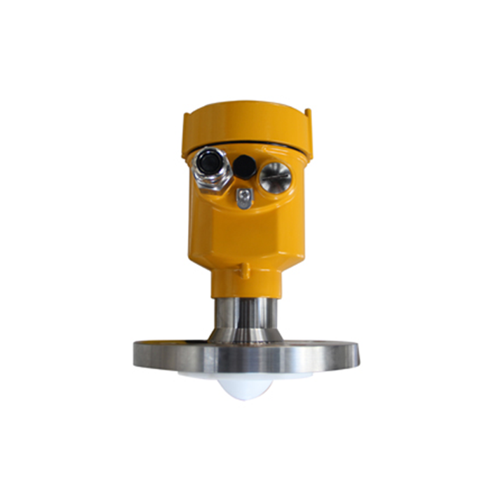
Because level equals the empty distance E minus the measured distance, an overstated distance reports a level that is low by the same amount. On an 8.000 m vapor space with er = 1.021, indicated distance becomes 8.000 * sqrt(1.021) = 8.084 m, so the reported level sits 83.6 mm below the true interface. The bias grows with the vapor space, so it is worst near empty, where low-level alarms are set. Both non-contact FMCW and guided wave radar see the effect, since the wave crosses the pressurized vapor. A fixed er entry, a reference reflector at a known distance or a reference probe in a stilling well provide the correction.
How a small permittivity change becomes millimeters
Wave velocity in the headspace is v = c0/sqrt(er) with c0 = 299 792 458 m/s. The transmitter times the echo and multiplies by c0/2, so indicated distance is d_read = d_true*sqrt(er) and the level error is dL = -d_true*(sqrt(er) - 1).
Worked example based on assumed site values (illustrative calculation, not field-measured data): an LPG sphere with an 8.000 m vapor space, saturated propane vapor at 8 bar g and 20 °C, and an assumed er = 1.021. Then sqrt(1.021) = 1.010445 and dL = -8.000 m * 0.010445 = -0.0836 m, or -83.6 mm. At 8 bar g with er = 1.015 the bias is -59.8 mm; at 12 bar g with er = 1.030 it reaches -119.1 mm. For level measurement in pressurized tanks the boundary condition is stable pressure, temperature and vapor composition; a pressure swing during filling invalidates one fixed er, so a reference-based correction is needed.
| Vapor condition | Pressure (bar g) | Assumed er (-, 20 °C) | sqrt(er) (-) | Level bias over 8.000 m (mm) |
|---|---|---|---|---|
| Dry air, vented | 0 | 1.0006 | 1.0003 | -2.4 |
| Ammonia vapor, light | 4 | 1.007 | 1.0035 | -28.0 |
| Propane vapor, 8 bar g | 8 | 1.015 | 1.0075 | -59.8 |
| LPG mixture, 8 bar g | 8 | 1.021 | 1.0104 | -83.6 |
| LPG vapor, upper | 12 | 1.030 | 1.0149 | -119.1 |
These are typical engineering reference values for saturated vapor, not product specifications. Confirm er for the actual gas composition and pressure against the current gas-property data sheet before entering a compensation value.
When ultrasonic is ruled out on sealed vessels
An ultrasonic level transmitter should not be specified for level measurement in pressurized tanks when vapor composition, pressure or temperature can change during the fill cycle. It times a mechanical wave whose speed depends on gas molecular weight, pressure and temperature. In a vented water tank one temperature compensation is enough; in an LPG or ammonia headspace there is no single sound speed, because gas density and composition move with saturation pressure. The acoustic path then adds an uncontrolled term far larger than the ±2 mm to ±10 mm accuracy usually required for overfill duties.
Two further boundaries make the method unusable. Sound does not propagate in a vacuum, so a vessel that can be evacuated loses its echo completely. Dense saturated vapor, foam or condensing droplets attenuate the pulse until the return vanishes while liquid is present. Where these conditions apply, the correct decision is a radar level transmitter with the vapor correction described above, not a better ultrasonic unit.
What cryogenic service changes in the wetted materials
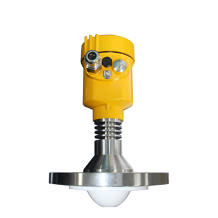
Liquid oxygen is stored near -183 °C at close to atmospheric pressure, while liquid ammonia or LPG may sit near -40 °C in refrigerated service. Austenitic stainless steels remain tough at these temperatures; ordinary carbon steels and many elastomers become brittle. The antenna, the process seal, the gasket and any coating must each be rated for the minimum metal temperature, not only the normal operating temperature, because a cool-down or a relief event can take the assembly below its design point.
Oxygen service adds a cleanliness requirement: wetted parts must be free of oil and grease, with the cleaning documented. A thermal extension keeps the electronics housing outside the cold zone, and its length must suit the certified ambient range; a housing rated to -40 °C cannot sit on a -183 °C nozzle. Condensation and ice on the antenna face are common during cool-down, so a purge or a sealed antenna with a verified low-temperature seal is normally specified. Confirm every wetted grade, the gasket compound and the certified ambient range on the delivered nameplate before installation.
How to leave usable range margin above the liquid
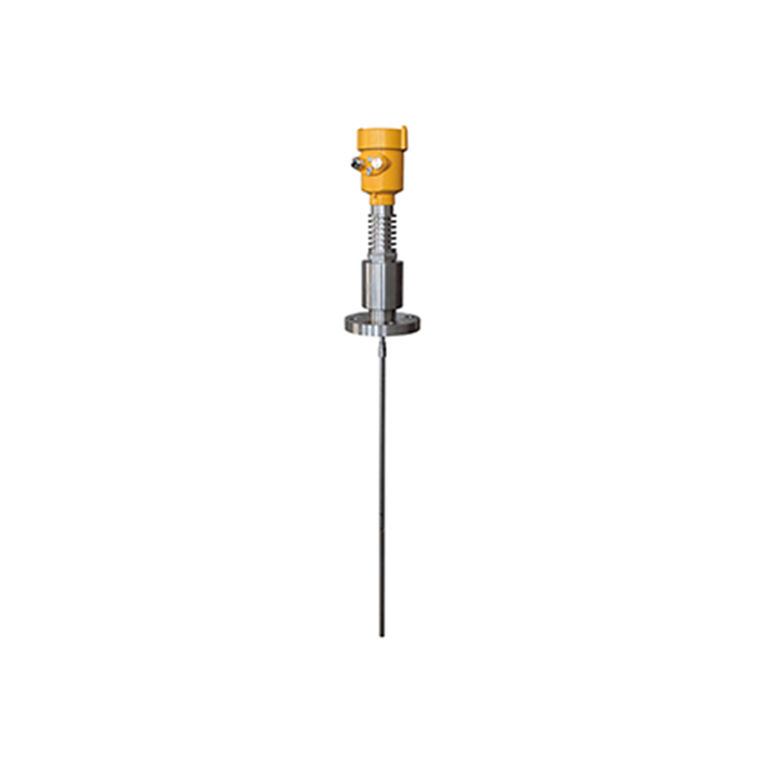
For level measurement in pressurized tanks, take an assumed 12.000 m empty distance E from the flange face to the tank floor. A blocking distance of 0.10-0.20 m applies to a flush 80 GHz lens antenna; 0.400 m is used here as a conservative case with an extended nozzle, to be verified on the current data sheet. That means the transmitter cannot report a level above 11.600 m. If the process high-high trip sits at 11.200 m and the required freeboard is 0.300 m, the margin between the trip and the measurement ceiling is 0.400 m, which clears the requirement. A 0.600 m nozzle would cut the margin to 0.200 m, a failed check.
The expression belongs on the order sheet: usable upper margin = E - blocking distance - maximum working level. On a 12.000 m vessel a 0.400 m margin is 3.3 % of span; on a vessel under 2.000 m the same blocking distance consumes 20 % of the span.
- Record E from the flange face, not from the roof.
- State the blocking distance for the ordered antenna and nozzle, not a catalogue minimum.
- Recheck the margin after any adapter, extension or insulation change.
- Keep the high-high trip below the measurement ceiling, not equal to it.
What the certificate must match on the delivered build
For level measurement in pressurized tanks, read the certificate against the ordered configuration, not the brochure. Gas group, temperature class, equipment protection level and certified ambient range must appear on the delivered nameplate and match the hazardous-area classification of the tank. A unit approved for -20 °C to +60 °C ambient cannot be installed where the housing sees -40 °C, even if the process seal is rated lower. An adapter, purge, heater or remote display added later must be covered by the approval.
| Check item | Acceptance criterion | Unit / condition | Evidence to request |
|---|---|---|---|
| Transmitter rated pressure | >= vessel design pressure (example 25) | bar g at 20 °C | Vessel data sheet |
| Process temperature range | -196 to +50 | °C depending on product | Vessel data sheet |
| Cryogenic service (LOX, LIN) | -196 to -150 | °C | Vessel data sheet plus cold-stretch test record |
| Headspace er | entered value plus source | -, at operating P/T | Gas-property data |
| Blocking distance | <= 0.400 | m, with ordered nozzle | Current data sheet |
| Upper measuring margin | >= 0.300 | m above high-high trip | Calculated order sheet |
| Explosion protection | Ex d / Ex i, gas group, T class | per hazardous area | Certificate and nameplate |
| Ambient at electronics | -40 to +60 | °C, certified | Certificate |
| Oxygen cleanliness | oil-free, documented | wetted parts only | Cleaning record |
Cross-check each row against the current data sheet and nameplate; request any missing value before release. The product page for each radar unit lists which configurations hold which certificate, and a technical article on approval markings explains the notation.
FAQ
Q1. Does level measurement in pressurized tanks need vapor compensation on every vessel?
No. It is needed only when headspace permittivity moves the reading beyond your error limit. Air at 1 bar over 2.000 m gives about 0.6 mm and can be ignored; saturated LPG vapor at 8 bar g over 8.000 m reaches roughly 84 mm. Verify er against current gas data.
Q2. Can an ultrasonic level transmitter replace radar on a sealed ammonia tank?
No, not when pressure or vapor composition changes during the cycle. Ultrasonic timing depends on one sound speed, and in a sealed ammonia headspace that speed moves with pressure, temperature and gas density. Vacuum removes the echo and dense vapor can absorb it. Use radar with vapor compensation instead.
Q3. Which low-temperature material check is most often missed?
The gasket and the process seal, not the antenna. Antenna grades are specified for cryogenic duty, but an elastomer gasket rated only to -20 °C will harden and leak at -40 °C. Check the minimum metal temperature of every wetted part, the housing ambient range, and an oil-free cleaning record.
Q4. How much upper margin should the order leave above the high-high trip?
At least 0.300 m is a common starting figure, but derive it from the blocking distance and vessel geometry. With a 12.000 m empty distance and a 0.400 m blocking distance, the measurement ceiling is 11.600 m; an 11.200 m trip leaves 0.400 m. Recalculate after any nozzle change.
Q5. Does guided wave radar avoid the vapor permittivity problem?
No. The pulse still travels through the headspace along the probe, so its velocity falls as er rises and the same sqrt(er) factor applies, though the geometry differs from a free-space FMCW unit. A reference probe or a fixed er entry is still needed on high-pressure duties.
Q6. What must the approval certificate match on the delivered unit?
The ordered configuration and the site classification. Check the protection concept, gas group, temperature class, equipment protection level and certified ambient range against the hazardous-area drawing, then confirm each appears on the nameplate. An adapter, purge or heater added later must be covered by the approval.
SUMMARY
Level measurement in pressurized tanks rests on three checks: correct the vapor permittivity, confirm the low-temperature wetted materials, and leave measurable range margin. The worked example shows an assumed er = 1.021 over an 8.000 m vapor space shifts reported level by 83.6 mm, far larger than the ±2 mm to ±10 mm usually required for overfill duty. The next step is to assemble the acceptance sheet and verify each row against the current data sheet before release.
Talk to a METRAVON engineer about this application
Send us the vessel design pressure and temperature, the stored product and its vapor composition, the nozzle height and the required upper freeboard. Our engineers will check the vapor-compensation setting, the wetted-material schedule and the certified range margin against those figures before suggesting a configuration.