


 Chinese
 Spanish
 Russian
 Portuguese
 French
 German
 Indonesian
 Thai
 Vietnamese
 Arabic
 Italian
 Turkish
 Polish
 Japanese


Stormwater wet-well level control has to distinguish waves from a sustained rise without delaying pump response. Increasing radar damping until the display looks quiet is not a complete solution. The accepted settings must leave enough hydraulic margin for detection, controller action and pump start during the site's relevant inflow conditions.
Allocate the response time before setting filters
Establish the level-rise cases from wet-well geometry, incoming flow and available pumping capacity. Include a pump unavailable for service and any downstream restriction. Calculate the storage between the operating setpoint and the limiting elevation using the actual geometry, not a nominal height percentage.
Review the full delay from a changing surface to effective pumping. Sensor filtering, controller scan, start sequencing and pump acceleration each contribute. Controller hysteresis and minimum run time serve different purposes from measurement smoothing; record their settings separately so a later change can be assessed.
Mount the radar for stormwater wet-well level control
The METRAVON MV-RD13S is a bracket-mounted radar option for atmospheric installations, with a 76 mm PTFE lens and nominal 3-degree beam. Choose its distance configuration from the highest and lowest expected water positions. A long-range version is not a substitute for adequate high-water clearance.
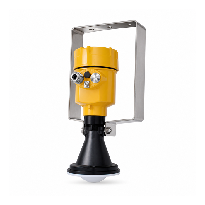
Aim away from the incoming jet, lifting chains and ladders through the whole measuring range. Check whether opening an access cover or using a nearby handrail moves the support. Do not accept a convenient mounting point that changes the reference whenever staff attend the station.
| Test | Observe | Acceptance focus |
|---|---|---|
| One pump | Drawdown and surface disturbance | The signal supports the intended stop level without avoidable cycling. |
| Peak inflow | Rising trend and start response | The measured response fits the available storage margin. |
| Pump fault | Command, feedback and standby sequence | Failure of one unit is not mistaken for successful drainage. |
| Network loss | Local sequence and remote display | Local control remains in its approved mode and remote data is marked stale. |
Validate the fault path as well as the level value
Compare a surveyed reference with the radar distance and then with the PLC engineering value. Exercise invalid measurement, lost communication and power restoration through an authorised test procedure. Do not create a real flooding condition to prove an alarm.
A continuous level sensor may drive several operational setpoints, but those setpoints are not independent measurements. Where the consequence of flooding requires a separate high-high safeguard, define its sensor, power, logic and test requirements independently.
Station-maintenance questions
Q1. Is a stilling tube always helpful?
No. Sediment or debris can restrict water exchange, leaving the tube level behind a rapidly rising wet well. A radar installation also needs a review of the tube bore, internal joints and sensor alignment: a calmer surface does not remove reflections from the tube itself. Obtain confirmation for the exact radar and tube arrangement before installation. Do not assume that a bracket-mounted MV-RD13S can be transferred into an existing tube without that review. Verify water exchange and cleaning access as well as the measured response.
Q2. Which evidence should be retained after a storm?
Keep the level and pump trends, alarms and any invalid-reading periods. Inspect the bracket and measurement path for debris or movement. Compare them with the commissioning baseline before changing filters or offsets.
Summary
For a wet-well radar quotation, provide the section drawing, inflow cases, pump sequence and required total response. Assess MV-RD13S against that duty, with mounting and fault tests included in the acceptance scope.
