


 Chinese
 Spanish
 Russian
 Portuguese
 French
 German
 Indonesian
 Thai
 Vietnamese
 Arabic
 Italian
 Turkish
 Polish
 Japanese


Radar vs Nucleonic Level Measurement: When Only a Source Works
A nucleonic gauge uses radiation attenuation along a designed source-detector path to infer level, density or another process variable. It can avoid a process penetration, but geometry, material density and equipment conditions still affect the result. Compare suitable alternatives and the full radiation-protection and licensing obligations with the responsible qualified specialists.
How the measurement works
A shielded source housing is clamped to one side of the vessel. A detector — a scintillation crystal or an ionisation chamber — is clamped to the other. Radiation passes through the steel wall, the product and the far wall, and the detector counts what arrives:
I = I₀ · e^(−μ · ρ · x)
In this idealised attenuation expression, mu is the mass attenuation coefficient, rho the density and x the material path length. An installed gauge also involves walls, internals, source-detector geometry and counting statistics. Usable span and calibration are design-specific, not universally restricted to 10-90% of vessel height.
The source and detector can be mounted outside the process boundary in a suitable design. Process temperature and pressure still affect mounting, insulation, shielding layout and the vessel; the detector and source assembly also have environmental limits.
| Item | Nucleonic assessment | Radar assessment |
|---|---|---|
| Measured signal | Radiation attenuation and counting response | Reflected electromagnetic signal |
| Process penetration | May not be required in an external arrangement | Depends on selected mounting; ordinary vessel duty needs a suitable path |
| Process effects | Density, geometry, internals and deposits in the beam | Reflection, vapour, deposits and path clearance |
| Temperature and pressure | Whole system, vessel and mounting conditions | Complete ordered assembly ratings |
| Performance | Calibrated geometry, statistics and required response | Model, antenna/probe and required response |
| Compliance | Applicable radiation authorisation and lifecycle controls | Applicable equipment, emissions, Ex and process requirements |
The regulatory burden, stated plainly
Determine the applicable national and local authorisation route before procurement. Some jurisdictions distinguish general and specific licences or registration conditions; do not describe every fixed gauge as the same licensed facility.
| Lifecycle topic | What the responsible specialist must establish |
|---|---|
| Authorisation | Applicable licence, registration or other regulatory route |
| Responsibilities | Competent radiation-protection oversight and trained users |
| Inventory and security | Required source records, access and movement controls |
| Testing and surveys | Applicable device, licence and regulatory requirements |
| Personnel monitoring | Risk- and jurisdiction-specific monitoring requirements |
| Maintenance and transport | Authorised service, shipping and emergency arrangements |
| End of service | Approved transfer, return or disposal route and records |
Use the regulator, licence conditions and authorised supplier to define the actual obligations, costs and lead times. Do not assume one leak-test interval, dosimetry policy or authorisation route applies everywhere.
The signal decays, and the clock is published
Radioactive activity decays according to the isotope half-life. Many systems compensate for decay within their design limits. Half-life alone does not set a mandatory recalibration, outage or replacement date.
| Isotope example | Approximate half-life | Engineering implication |
|---|---|---|
| Caesium-137 | About 30 years | Assess actual source activity, geometry, compensation and counting margin |
| Cobalt-60 | About 5.27 years | Assess actual source activity, geometry, compensation and counting margin |
For a given source, activity is approximately halved after one half-life. The effect on measurement uncertainty and response depends on the detector, geometry, background, compensation and count integration. Review performance and replacement through the approved service process rather than a fixed year-six rule.
Include the actual authorised inspection, service and end-of-life arrangements in the lifecycle study. Do not handle or relocate a source or alter shielding as an ordinary instrument replacement task.
When an external attenuation measurement deserves review
The following constraints can make an external attenuation system worth assessing. They do not prove it is the only possible technology.
No usable penetration. Assess external attenuation and other suitable non-intrusive methods with the actual vessel, wall, lining and required variable. Absence of a nozzle alone does not establish that gamma is the only option.
Demanding temperature or pressure. Compare complete purpose-rated alternatives and the source/detector environmental design. A generic extension or purge cannot raise a radar assembly rating to 450 degrees Celsius.
Obstructed measuring paths. Vessel internals can interfere with radar and also alter a radiation attenuation path. Include their geometry, material and possible movement in the calibrated system design.
There is also a fourth, softer case: products where the surface is not a surface. A froth, a boiling bed, a fluidised solid or a multi-phase mixture may have no defined level for radar to measure, while gamma reports the average density along its path.
Where radar has replaced the source
A substitution study should compare the actual required variable and available technologies, not assume an industry-wide replacement trend.
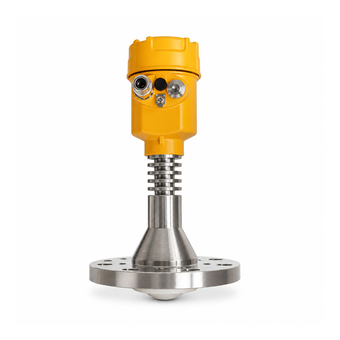
- Mounting access. Check the actual radar antenna or probe arrangement against the existing opening; do not use a universal 50 mm fit rule.
- Temperature. Verify a purpose-rated complete assembly and its installation limits. Remote electronics and cooling arrangements do not upgrade an unqualified process seal.
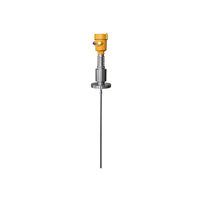
- Low-reflection products and interfaces. Suitable guided-wave or free-space systems may be options within their application limits. Define layer and profile requirements rather than applying a universal cutoff.
- Fouling and abrasion. Both methods can avoid a long immersed probe in suitable designs, but deposits, vessel buildup and measuring-path changes can still affect them.
- Total cost. Compare the actual equipment, installation, approvals, maintenance and decommissioning scope with dated quotations and a defined study period.
Base the substitution decision on the measured quantity, credible operating conditions, available geometry, uncertainty, response and compliance. No single temperature/pressure threshold makes either system automatically acceptable.
Minimising the source when you keep one
Have the qualified authorised system supplier and radiation-protection team assess optimisation and required worker protection. Any design change must preserve the approved device, vessel integrity and regulatory conditions.
Geometry. The attenuation path is part of a specialist design. Do not thin a pressure wall, add a standpipe or relocate a source to reduce activity without the required vessel and radiation approvals.
Detector and source design. Assess efficiency, background, response and required activity together through the authorised supplier. A larger detector does not automatically reduce the regulatory obligations.
Location and shielding. Access, beam direction, shielding and emergency arrangements must follow the approved design and surveys, not a generic instruction to mount the source away from a walkway.
Frequently asked questions
Q1. Can radar replace a nucleonic level gauge?
Sometimes. Assess whether a suitable radar can measure the required variable over the full process envelope and available path. There is no universal nozzle/450-degree/40-bar substitution rule.
Q2. Does a nucleonic gauge need a licence?
The applicable authorisation depends on jurisdiction, device and activity. Establish the licence, registration or other conditions with the regulator and authorised supplier before procurement or any source-related work.
Q3. How often does a nucleonic source need replacing?
Half-life does not set one replacement interval. Use the approved system performance, activity, counting margin, service requirements and regulatory conditions to plan any authorised replacement.
Q4. Is a nucleonic gauge dangerous to plant personnel?
Ionising-radiation hazards require the approved shielding, access, training, surveys and applicable monitoring. A generic product guide cannot guarantee personnel dose or replace the responsible radiation-protection assessment.
Q5. Which is more accurate, radar or a nucleonic gauge?
Compare the actual measuring variable, calibrated system uncertainty, geometry and required response. A universal millimetre-versus-percent ranking is not an acceptance specification.
Q6. Can a nucleonic gauge measure interface?
Suitable attenuation systems can measure selected interfaces or density profiles. Guided-wave and other principles are alternatives where their phase, geometry and signal conditions are met.
