


 Chinese
 Spanish
 Russian
 Portuguese
 French
 German
 Indonesian
 Thai
 Vietnamese
 Arabic
 Italian
 Turkish
 Polish
 Japanese


Floating Roof Tank Level Measurement: Radar in the Gauge Well
Floating roof tank level measurement must distinguish liquid level from roof position. A radar on a fixed, tank-referenced still pipe can measure product through an approved gauge-well arrangement. A device carried by the floating roof measures distance relative to that moving roof unless an independent position reference is added. Confirm the tank drawing and measurement datum before selecting the mounting.
What the gauge well actually shows
The gauge well is a vertical pipe through the roof, with inside diameter and antenna specified together, with holes or slots so product and vapor move freely. Radar installed on top of the well measures the level inside it. That is normally the cleanest echo on the tank — a still, flat surface in a narrow pipe with almost no vapor turbulence.
But the level inside the well is only useful if the well communicates honestly with the tank. Verify three things during design review:
| Well feature | What to check | Failure it prevents |
|---|---|---|
| Hole/slot area and position | Total open area and distribution along the working range | Stagnant product in the well lagging the true level |
| Cleanliness | History of clogging by wax, scale or product skin | A well that reads a frozen level while the tank moves |
| Roof penetration | Seal around the well at the roof plate | Product or vapor bypassing the seal |
During a controlled fill, compare the well reading with an approved independent reference at several levels. Manual gauging is appropriate only through designated access under the site procedure; confirm that well communication is fast enough for the required alarm response.
Roof tilt is real, and it matters more than transmitter accuracy
A large floating roof is not a rigid plane. It tilts as product is drawn under one side and as pontoons take up different loads. The allowable tilt and roof displacement come from the tank design and operating assessment; what matters for safety is that the alarm elevation is set against the highest point the product or roof can reach, not against the average level.
The liquid surface and the floating roof are different references. A roof can tilt, stick, land or lose buoyancy while the liquid gauge remains correct. Establish the lowest limiting elevation from the roof, seal and tank design; then subtract filling rise during detection and shutdown, measurement uncertainty and the required operating margin. Roof-position or tilt monitoring may be needed separately.
Worked example. Suppose the approved limiting elevation is 19.2 m, the required freeboard is 0.30 m, the design-derived roof allowance is 0.06 m and measurement uncertainty is 0.03 m. These terms give 18.81 m before adding any further setback for filling during detection and shutdown. It is not a complete high-high setpoint until the fill rate, response time and final-element closure have been included.
External floating roofs: measure the roof or the product
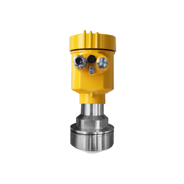
An external floating roof tank normally has no fixed roof above the floating deck. Product level is commonly measured in a stationary still pipe supported from a fixed tank reference. A fixed external support may instead track a target on the roof for roof-position monitoring. An opening or gap near the pontoons is not automatically an unobstructed, representative liquid-measurement path.
Tracking a target on the roof reports roof position, not directly liquid level. The relationship changes with buoyancy, roof load, landing and abnormal roof conditions. A roof can sink into the product; its position alone is therefore not a generally acceptable substitute for an independent liquid overfill measurement. Validate each function against its own required variable.
Pick the variable you actually need to control, then pick the mounting. Do not accept a default drawing that shows a transmitter "somewhere on top."
Alarms and independence on a floating roof
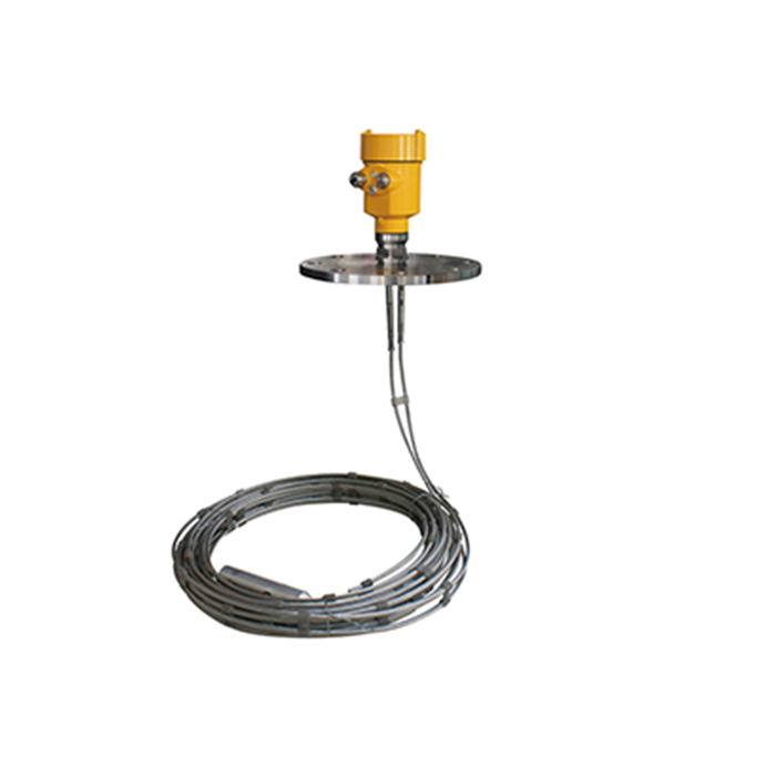
Overfill protection on floating roof tanks follows the same independence logic as any tank: the high-high layer must not share a single failure point with the control layer. A practical architecture is the continuous gauge-well radar for control and inventory, plus an independent point switch — float or vibrating fork in a separate well or nozzle — wired to a separate trip input.
Watch for two shared-cause traps specific to floating roofs:
Both devices reading from the same clogged gauge well fail together.
Both devices supplied from the same junction box on the roof lose power together when the roof moves against a cable.
Questions from floating roof projects
Q1. Can one transmitter cover both inventory and overfill?
It can feed both functions as information, but the safety review should still treat a single device as one layer. Use a second, independent sensor for the high-high trip.
Q2. Does the gauge well need its own stilling function?
The well itself is the stilling arrangement. Its holes must let the level follow the tank within the required response time — test this during commissioning by comparing against a dip tape during a controlled fill.
Q3. What happens to the reading when the roof lands on its legs?
On an EFR the product level continues below the roof landing elevation; a suitably configured gauge-well radar can keep reading while liquid remains within its usable measuring range; the well does not have to be completely full. Confirm the well extends low enough for the ranges you need at low inventory.
Related technical guides
- Radar Level Transmitter Retrofit on an Existing Tank: What Can Be Reused
- How to Specify a Radar Level Transmitter: The 14 Fields That Decide the Quote
Discuss your measurement application with METRAVON
