


 Chinese
 Spanish
 Russian
 Portuguese
 French
 German
 Indonesian
 Thai
 Vietnamese
 Arabic
 Italian
 Turkish
 Polish
 Japanese


Dairy CIP tank level measurement must remain understandable as tanks receive, heat, circulate and recover different cleaning solutions. The level signal tells the controller how much space is occupied; it does not identify a chemical, establish its concentration or prove that a cleaning cycle has achieved its purpose.
Separate the Supply Tank From the Return Route
Start with the CIP flow diagram. Identify the water, chemical-solution and recovery tanks, their permitted return routes and the measurements used to accept or reject recovered liquid. A rising level in the expected tank can coexist with an incorrect valve route or unsuitable recovered solution. Level permissives therefore need the relevant route and process checks rather than replacing them.
For each tank, document normal contents, maximum cleaning exposure, dosing location, heating method and return entry. A sensor above a quiet storage tank has a different duty from one exposed to a hot, splashing return. Assess the conditions at the antenna and seal, not only the nominal temperature of fresh solution.
Dairy CIP Tank Level Measurement During Changeover
| State | Observe | Control check |
|---|---|---|
| Charging | Liquid entry, foam and response near the fill stop. | Stop admission with adequate space for delayed inflow. |
| Heating | Condensation, changing surface conditions and usable pump intake. | Prove the required liquid condition through the approved heater permissive. |
| Recovery | Return route, solution identity and rapid level rise. | Combine level with the separate criteria for accepting recovered solution. |
| Draining | Residual heel and any loss of a usable echo. | Do not equate zero displayed level with a fully drained vessel. |
Define how the PLC treats an invalid reading in every state. Holding a previous value may be acceptable for a clearly marked historical trend; it is not evidence that a heater remains covered or that space remains for incoming solution. The site's approved cause-and-effect should determine the action for a missing measurement.
Temperature Rating Is Only One Part of the Assembly
The METRAVON MV-RD12G lists a 32 mm PTFE lens, a 0.1-30 m liquid measuring interval and a high-temperature process assembly. Its published process temperature extends to 200 deg C, subject to the selected seal, connection and concurrent pressure. That specification is not an approval for every caustic, acid or disinfectant mixture used in a dairy.
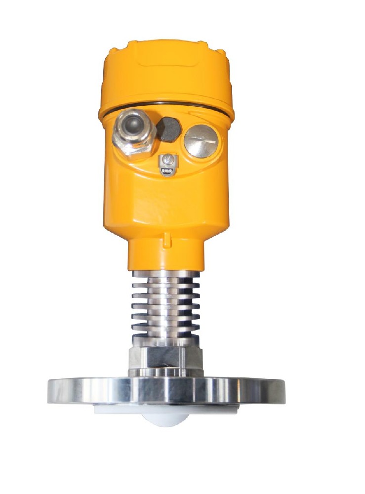
Give the supplier chemical names, concentrations, exposure temperatures and cycle durations. Review all exposed parts and the installed seal, including any adaptor. Confirm that the process connection drains and can be cleaned as required. Do not enclose the heat-dissipating section in tank insulation unless the approved installation permits it; the electronics also have their own ambient limit.
If the actual duty remains within the selected MV-RD12 configuration, a high-temperature version may be unnecessary. Select from the complete operating cycle, not from a higher headline rating.
Test the Route, Reading and Permissive Together
First check the vessel datum, distance-to-level conversion and receiver scaling. Then observe an approved water trial through charging, circulation, return and drain. Confirm which behaviours still need verification with the intended solutions. Record valve state and temperature beside the level trace so a return-path problem is not attributed to the instrument.
For an ordered RS485 interface, use the supplied Modbus RTU register and status definitions. For a 4-20 mA installation, verify both measurement scaling and the agreed fault indication at the receiving input. A successful local display test does not verify the heater or transfer permissive.
CIP Instrument Questions
Q1. Can level confirm that a recovery tank contains the correct solution?
No. It confirms occupied height when the measurement is valid. Solution identification and acceptance require the plant's designated measurements and routing checks. Keep those conditions visible in the control logic instead of inferring chemistry from the tank name.
Q2. Should the reading remain active while the tank is being washed?
Retain the data if useful, but identify the washing state and test whether spray or foam invalidates the target. The controller should not treat an unqualified cleaning reading as production inventory. Define the conditions for returning to normal measurement after the cycle.
Summary
Specify the instrument around the CIP sequence, chemical exposure and intended permissives. For a configuration review, provide the tank and return-line drawings, solution schedule and control sequence. The resulting offer should identify the process assembly, electronics and tests needed before the level signal is used in operation.
