Chinese
 Spanish
 Russian
 Portuguese
 French
 German
 Indonesian
 Thai
 Vietnamese
 Arabic
 Italian
 Turkish
 Polish
 Japanese

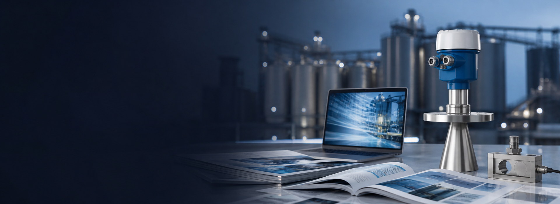
The appeal of a clamp-on level sensor is simple: it measures from outside the tank, so no nozzle is cut, no seal is broken and no process fluid is exposed during installation. The risk is equally simple: the ultrasonic pulse must travel through the vessel wall, and if that wall attenuates or scatters the signal too much, the reading never appears. Through-wall feasibility is therefore a verification problem before it is a measurement problem, and it should be settled with a site test rather than a catalogue guess.
Why the Wall Is Part of the Instrument
Unlike a non-contact radar that looks down through gas, a clamp-on ultrasonic level sensor couples its pulse into the steel or plastic wall, through it, into the liquid, and back. The wall is not a mounting convenience; it is the first and last acoustic element in the path, and its thickness, material and internal condition decide whether a usable echo returns. A sensor specified only from the liquid properties will fail on a wall it was never asked about, which is the most common clamp-on disappointment.
This is also why clamp-on competes with, rather than replaces, intrusive methods. Where a nozzle exists and accuracy matters, a guided-wave or radar transmitter avoids the wall entirely. Clamp-on earns its place when cutting a nozzle is forbidden, when the tank cannot be opened, or when a quick retrofit must happen without stopping the process. The feasibility test is what separates those two cases.

Stage 1: Wall Material and Thickness
The first stage checks whether the wall can carry the pulse at all. Steel and most metals transmit ultrasound well, but very thick walls increase the path and reduce the returning energy; thin plastic walls can work but may ring and blur the echo. As a screening rule, carbon-steel walls from about 6 mm to 30 mm are routinely measurable, while walls above roughly 50 mm or made of acoustically lossy or layered material need a specific probe and a trial. Between 30 mm and 50 mm, treat the wall as trial-only: obtain the probe-specific wall table and run a coupled test before quoting. The exact limit depends on the probe frequency, so confirm against the supplier's wall table.
The wall also has to be accessible and clean on the outside, with a flat coupling area free of heavy insulation or loose scale. A couplant is used to remove the air gap between probe and wall; without it the air interface reflects almost all the energy back. Stage 1 passes when the wall type, thickness and external surface are all within the probe's stated range, and fails when any one of them is outside it.
Stage 2: Through-Wall Attenuation Budget
Stage 2 turns the wall check into numbers by estimating how much signal survives the round trip. Each interface and the wall itself remove energy; the remainder must still exceed the sensor's minimum detectable level. The worked budget below uses assumed values and is a calculation method, not METRAVON measured data.
Illustrative calculation, assumed site values:
Wall: steel, 10 mm thick, loss ≈ 2 dB per pass
Round trip through wall: 2 passes → 4 dB
Internal coating: 5 mm, loss ≈ 3 dB per pass → 6 dB round trip
Liquid path and return loss: ≈ 5 dB
Total attenuation: 4 + 6 + 5 = 15 dB
Probe launch margin: 25 dB above minimum detectable
Remaining margin = 25 dB − 15 dB = 10 dB. Result: with these assumed values the echo survives with 10 dB to spare, so the duty passes stage 2. Boundary condition: a 50 mm wall (≈ 10 dB per pass, so 20 dB round trip) plus the same 11 dB of coating and liquid loss totals 31 dB against a 25 dB budget, a 6 dB shortfall and a definite fail rather than a marginal one. That is why thick, insulated or clad walls are the usual stage-2 rejects.
Stage 3: Internal Condition and Coupling
Stage 3 checks what is happening on the inside, because a clean wall still fails if the liquid side defeats the echo. Heavy internal buildup, a persistent foam layer, intense agitation, or a dip pipe or agitator within about 200 mm of the probe path, all scatter or absorb the returning pulse. These are not wall problems and will not show up in stage 1, which is why they need their own test with the tank in its normal operating state, not empty and still.
The external coupling is re-verified here as well: the couplant must stay bonded through the test, and the probe must remain clamped without movement. A reading that drifts as the probe is gently pressed or released is telling you the coupling, not the level, is the variable. Stage 3 passes when a stable echo holds through a level change with the tank running, and fails when the signal only appears under ideal, unrepresentative conditions.
Tank Conditions to Judge Unusable Up Front
Some tanks should be marked not-feasible before any test, because the failure is structural. Walls thicker than the probe's range, or made of acoustic foam, sandwich or heavily clad construction, defeat the pulse by design. Tanks with a permanently turbulent or foaming contents where no stable surface exists will give a reading that is stable and wrong. And vessels whose external surface cannot be reached or kept clean cannot be coupled at all.
Also judge unusable any duty that needs high accuracy on a tank whose wall thickness varies point to point, because the through-wall delay then varies with probe position and the zero shifts as the sensor is moved. Clamp-on is a robust retrofit and inventory tool, but it is not the right answer where the wall itself is the problem; an intrusive or radar-through-nozzle method should be specified instead.
| Tank condition | Practical threshold | Verdict |
|---|---|---|
| Wall thickness | > 50 mm carbon steel | Usually not feasible |
| Wall construction | Foam, sandwich or clad | Not feasible |
| Contents state | Permanent foam or heavy agitation | Not feasible |
| External surface | Insulated or not reachable | Not feasible |
| Thickness variation | > ±3 mm point to point | Zero shifts with probe position; re-verify zero at the final clamp position |
| Required accuracy | < ±5 mm on varying wall | Consider intrusive |
When Clamp-On Should Not Be Chosen
Clamp-on should be declined when the accuracy requirement is tight and the wall is uncertain, because the through-wall path adds an error source no calibration removes. It should also be declined where a nozzle already exists and a continuous transmitter would give a cleaner, cheaper long-term signal, since clamp-on's main advantage, no nozzle, is then wasted. Forcing clamp-on onto a thick-walled, turbulent, clad tank produces a project that passes a hopeful bench test and fails the plant.
The honest alternative is to treat clamp-on as one option in a short list, not a default. Where it passes the three-stage test it is genuinely the fastest, safest retrofit; where it fails, saying so early saves a site visit and a disappointed operator. The feasibility method exists precisely to make that call on evidence rather than optimism.

FAQ
Q1. Does clamp-on work on any tank if I just couple it well?
No. The wall must be within the probe's thickness and material range, and the inside must give a stable echo. A thick, clad or lossy wall, or a permanently turbulent or foaming liquid, defeats the pulse regardless of coupling quality. Run the three-stage test before quoting.
Q2. How thick a wall can a clamp-on sensor handle?
As a screening rule, carbon steel from about 6 mm to 30 mm is routinely measurable, with some probes reaching further; walls above roughly 50 mm or layered, clad or foam constructions usually fail, and 30 mm to 50 mm is trial-only. Confirm against the specific probe's wall table rather than assuming.
Q3. Why does internal coating matter if the sensor is outside?
The pulse still crosses the internal wall surface into the liquid and back, so a 5 mm coating adds attenuation on each pass, about 3 dB per pass in the worked example. Heavy buildup can consume the margin and cause intermittent or lost echoes even on a clean external wall.
Q4. Can clamp-on replace a nozzle-mounted radar?
Only when cutting a nozzle is forbidden or the tank cannot be opened. Where a nozzle already exists and accuracy matters, an intrusive or radar transmitter avoids the wall path entirely and is usually the better long-term choice. Clamp-on wins on retrofits without nozzles.
Q5. My reading drifts when I press the probe. What does that mean?
It means the external coupling, not the level, is the variable, because the couplant bond or clamp is unstable. Re-establish a bonded, fixed coupling and re-run stage 3; if the signal only appears under pressure, the installation has not passed.
Q6. When should I abandon clamp-on and pick another method?
Abandon it when the wall is outside the probe range, when the contents are always turbulent or foaming with no stable surface, or when the duty needs tight accuracy on a varying-thickness wall. Specify an intrusive or nozzle radar instead, and say so before a site visit.
SUMMARY
A clamp-on ultrasonic level sensor is feasible only after a three-stage test of wall material and thickness, through-wall attenuation and internal condition; in a worked budget a 10 mm steel wall plus 5 mm coating consumes 15 dB of a 25 dB margin and passes, while a 50 mm wall fails by about 6 dB. Judge thick, clad, turbulent or unreachable-wall tanks unusable before testing.
Talk to a METRAVON engineer about this application
If you are considering a no-nozzle retrofit, send us the tank wall material and thickness, the liquid and whether it foams or agitates, and a photo of the external surface, and we will run the three-stage feasibility check and tell you plainly whether clamp-on will work.