


 Chinese
 Spanish
 Russian
 Portuguese
 French
 German
 Indonesian
 Thai
 Vietnamese
 Arabic
 Italian
 Turkish
 Polish
 Japanese


Clinker silo level measurement must account for the temperature reaching the radar assembly, not merely the temperature on the control-room display. Hot material, rising gas and heat conducted through the roof connection can expose different parts of the instrument to different conditions. Select the assembly only after those operating cases are defined.
The hot-solids model has a specific limit
METRAVON MV-RD21G is specified for bulk solids at -40 to 200 deg C, using a 76 mm PTFE lens and a nominal 3-degree beam. Its published process-pressure range is -0.1 to 0.3 MPa. These are configuration references, not permission to operate every flange, seal and housing at all listed extremes simultaneously.
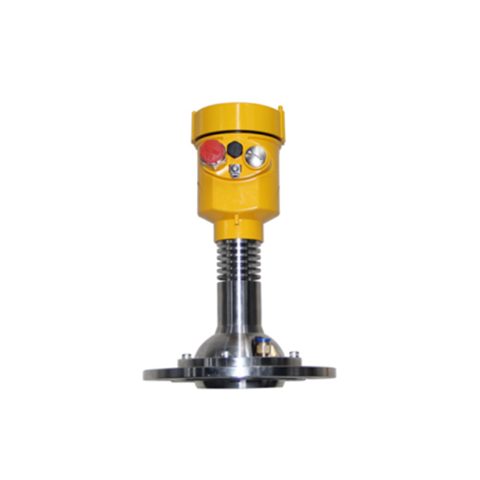
If the credible exposure exceeds the specified limit, this model has not been established as suitable. Do not substitute a liquid radar solely because its page lists a higher temperature. The antenna, solids application, mounting and pressure construction still require a separate review.
Locate clinker silo level measurement outside the falling stream
Show the transfer chute and expected pile positions on the silo section. The instrument needs to observe the material surface without receiving direct impact or repeatedly seeing the incoming stream. A rigid, accessible mounting point also helps maintenance staff restore the same orientation after removing the assembly.
Check the path at low level as well as near full. Roof members and wall deposits that appear clear at short distance may enter the illuminated region farther down. Save the accepted echo and mounting orientation so a later disturbance can be compared with a known installation.
| Case | Evidence to obtain | Effect |
|---|---|---|
| Normal feed | Material and gas temperatures at the proposed location | Defines the thermal duty, including the connection. |
| Hot restart | Expected excursions after an upset or shutdown | May exclude an assembly that suits steady operation. |
| Near full | Pile height and remaining feed after a stop command | Determines the required operating headroom. |
| Maintenance | Access, isolation and removal clearance | Prevents the installed position from becoming unserviceable. |
Allow for material already in transit
The surface may continue rising after a conveyor stop command because material remains on the conveying route or in the chute. Establish that run-on quantity from the actual system and check it against available capacity. Instrument damping, controller scan and drive response add further delay; none should be assumed negligible without a functional test.
Commission the level indication and the protective functions as separate tasks. Compare local distance with the PLC scaling, then test the approved response to invalid measurement and high level. Do not create a dangerous overfill to demonstrate a trip; use the site's authorised test method.
Questions before ordering
Q1. Is a cooling arrangement automatically included?
No. The model name does not define a plant cooling utility, purge arrangement or its failure response. Any proposed accessory needs a drawing, utility requirement and confirmation that it is compatible with the selected instrument.
Q2. Can a higher range compensate for a weak return in heavy dust?
A longer listed range does not establish additional usable echo margin in that condition. Review the antenna position and actual echo during feed, then qualify the proposed configuration with the relevant material and dust exposure.
Summary
For a clinker-silo radar review, provide the thermal cases, chute geometry, empty distance and run-on behaviour. MV-RD21G should remain a conditional selection until the full assembly and the filling response have been checked.
