


 Chinese
 Spanish
 Russian
 Portuguese
 French
 German
 Indonesian
 Thai
 Vietnamese
 Arabic
 Italian
 Turkish
 Polish
 Japanese


Ballast Tank Level Measurement on Ships
Ballast tank level measurement is judged in port by surveyors and at sea by a control system, and the two audiences want different things. In port the tank is still and almost any principle works. At sea the same surface is a moving, foaming slope that can leave the sensing point dry in one roll and submerged the next. Design for the sea state, then check that the in-port readings still satisfy survey.
Sloshing is the central problem
A partially filled tank on a rolling vessel develops surface motion that is periodic and large — hundreds of millimetres of free-surface travel is normal, and resonant slosh in a tank whose natural period sits near the vessel's roll period can be worse. Any measurement philosophy must answer one question: what do we want from a surface that never holds still?
Three honest answers:
Point protection — high and low alarms must meet the vessel’s approved response requirement despite slosh. A validated persistence delay may reject brief wetting, but it also delays action. Select the delay from fill rate, stopping time, sea trials and classification requirements, rather than applying a universal 2–5 second setting.
Averaged level — ballast control may use a filtered reading over representative vessel motion. Its relationship to quantity still depends on tank shape, sensor location, trim and heel. Determine damping and quantity corrections from the operating requirement and trials; an average height alone is not a mass-distribution measurement.
Ullage/quantity — for cargo custody, measurement happens in port under still conditions with established procedures; at-sea numbers are indicative. Mixing these three purposes in one instrument is where ballast systems go wrong.
Where each principle survives at sea
| Principle | Behaviour to assess at sea | Installation requirement |
|---|---|---|
| Float gauge | Local surface motion and mechanical travel | Approved mounting, guidance and verification |
| Pressure or bubbler | Local pressure, acceleration, density, trim and heel | Tap geometry, air supply where applicable, validated filtering |
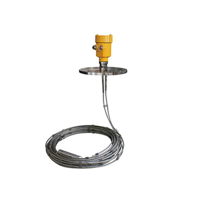
| Guided-wave radar | Moving surface, foam and probe loading | Usable range, support and actual dynamic response |
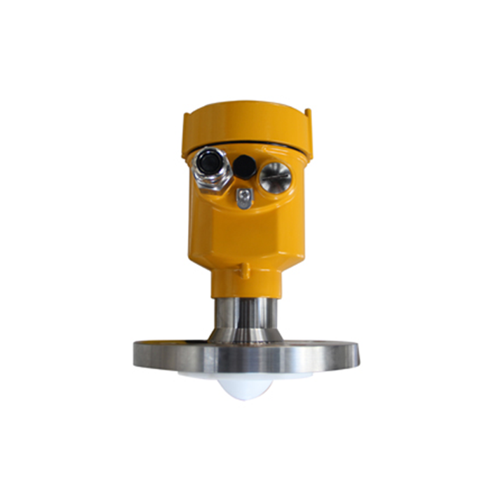
| Non-contact radar | Changing surface angle and structural echoes | Clear path; assess any supported stilling arrangement |
| Capacitance | Wetting, deposits and changing medium | Correct calibration and approved switch or transmitter interface |
| Ultrasonic | Gas path, humidity, foam and geometry | Verified environmental and dynamic suitability |
The bubbler deserves respect in ballast service: it has no electronics in the tank, can support a suitable filtered pressure measurement, and its weak points — air supply reliability and density sensitivity — are well understood by marine engineers. Its modern weakness is the air supply: on unmanned machinery schedules, a compressor or dryer failure disables every bubbler on board together. That shared dependency belongs in the failure analysis.
Deep tanks, cofferdams and wing tanks: geometry decides reach
Ship tanks are tall and narrow with structural members inside: transverse webs, lightening holes, swash bulkheads. A sensor's line of sight or probe path must be checked against the actual section drawing:
A probe or beam that passes through a lightening hole can read the splash climbing the hole edge during roll.
Swash bulkheads calm the surface locally but divide the tank; a sensor in one compartment reports that compartment.
Tank-top mounting saves cable runs but may place the sensor exactly where deck structure blocks the path.
For non-contact radar on ballast service, a perforated stillpipe from the tank top into the tank gives the beam a quiet path and protects it from structure; the perforations must be sized and positioned so the pipe level follows the tank within the alarm response budget.
Approval and installation realities
Confirm the type-approval and installation requirements of the vessel’s classification society and flag administration. Approval must cover the exact equipment, function and environmental category; it is not automatically a fire-safety, hazardous-area or custody certificate. For ballast tanks also check:
the sensor's rating for the tank's zone classification — ballast tanks adjacent to cargo tanks can carry gas-entry requirements;
cable entry and sealing against repeated immersion pressure cycles at tank top;
materials against seawater and, for cargo-adjacent tanks, against cargo vapors;
redundancy philosophy: which readings the vessel can operate without, for how long.
A sensor that freezes its last value without a bad-quality flag is worse than one that fails to a defined alarm state; define failure behavior in the specification.
Questions from marine projects
Q1. Is radar better than floats for ballast control?
For control and remote indication, radar or bubbler systems transmit cleanly and average well. Float gauges remain excellent for local visual verification — many surveyors still trust a mechanical tape they can see. Use them together rather than arguing about a winner.
Q2. How long should damping be at sea?
Derive it from the observed motion and the required control and alarm response, then validate during trials. Continuous filtering and switch persistence delays serve different purposes; neither may consume the available shutdown margin without review.
Q3. Can cargo tank instrumentation serve ballast needs?
Some approved platforms cover several tank duties. Check each tank’s medium, geometry, motion, hazardous-area classification, accuracy and alarm requirements. A cargo-instrument label alone does not establish ballast suitability, and sharing must not defeat required independence.
