


 Chinese
 Spanish
 Russian
 Portuguese
 French
 German
 Indonesian
 Thai
Thai Vietnamese
 Arabic
 Italian
 Turkish
 Polish
 Japanese

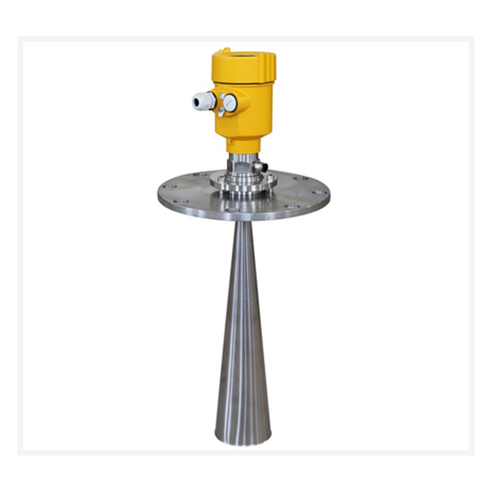
Radar level transmitters are widely used for continuous level measurement in industrial tanks, water treatment systems, chemical processes, petroleum storage, food production, mining and bulk-solid silos. According to the measurement principle and probe structure, industrial radar level measurement can generally be divided into non-contact radar and guided wave radar.
A non-contact radar transmitter sends electromagnetic waves through an antenna toward the material surface and calculates the distance from the reflected signal. Guided wave radar, by contrast, directs the radar pulse along a rod or cable. Both technologies use radar principles, but their installation methods, suitable applications and maintenance requirements are different.
1. How Does a Radar Level Transmitter Work?
A radar level transmitter emits high-frequency electromagnetic waves toward the process surface. When the radar signal reaches a liquid, slurry or bulk-solid surface, part of the signal is reflected back to the instrument. The transmitter analyzes the travel time or frequency difference between the transmitted and reflected signals to calculate the distance to the material surface.
When the tank or silo reference height is known, the actual level can be calculated as:
Level = Reference Height − Distance from Radar to Material Surface
Modern industrial radar instruments commonly use pulse radar or FMCW (Frequency Modulated Continuous Wave) technology. Because radar uses electromagnetic waves, it does not require air as a propagation medium and can operate in vacuum conditions. It is also generally less sensitive than ultrasonic measurement to changes in air temperature, pressure and airflow.
2. What Are the Main Types of Radar Level Instruments?
Non-Contact Radar Level Transmitter
The antenna is installed above the material and does not remain in direct contact with the process medium. It can be used for liquids, slurries, powders, granules and selected bulk solids.
Guided Wave Radar
The radar pulse travels along a rod or cable and therefore uses a contact measurement structure. It is suitable for selected low-dielectric liquids, foam applications, interface measurement and bypass chambers.
Non-contact radar is useful where direct contact with the process medium should be minimized, while guided wave radar can provide advantages in certain foam, interface and narrow-vessel applications. The final choice should consider the process medium, temperature, pressure, foam, installation space and maintenance conditions.
3. Main Advantages of Radar Level Transmitters
Non-Contact Continuous Measurement
Non-contact radar antennas do not need to remain immersed in the medium, reducing direct exposure to corrosion, wear and product buildup.
Wide Temperature and Pressure Capability
Depending on the specific model, radar instruments can be used in atmospheric, vacuum, pressurized and high-temperature processes.
Suitable for Liquids and Solids
Applications include water, oil, chemicals and slurries, as well as cement, grain, minerals, coal and other bulk solids.
Narrow Beam Reduces Interference
High-frequency radar can produce a narrow measurement beam, helping avoid vessel walls, pipes, structural beams and other internal obstacles.
Not Directly Affected by Density Changes
Radar level measurement does not depend on hydrostatic pressure, so changes in liquid density do not directly create the same level error seen in hydrostatic measurement.
Easy Automation Integration
Depending on the model, interfaces may include 4–20mA, HART and RS485 Modbus RTU for integration with PLCs, DCS, RTUs and SCADA systems.
4. What Are the Limitations of Radar Level Measurement?
Although radar has a wide application range, it is not automatically suitable for every process without proper selection and installation. Medium reflectivity, foam, antenna buildup, internal structures and mounting position can still affect measurement performance.
Low-Dielectric Media
Weakly reflective media may require higher dynamic range or a more suitable radar frequency and antenna.
Thick Foam
Dense foam can attenuate radar signals, so radar should not be assumed to penetrate all foam without limitation.
Heavy Antenna Buildup
Heavy coating, deposits or condensation can reduce echo quality and should be evaluated together with antenna design and signal processing.
Complex Internal Structures
Agitators, heating coils, support structures and beams can create false echoes.
Installation Position
Even a high-performance radar transmitter can produce unstable measurements if installed in an unsuitable position.
5. What Is the Difference Between High-Frequency and Lower-Frequency Radar?
Radar frequency affects wavelength, antenna size, beam angle and suitability for different process conditions. Common industrial radar technologies include 24/26GHz and 80GHz non-contact radar, while lower-frequency products are also used in selected applications.
Higher frequency means shorter wavelength. With a similar antenna size, higher-frequency radar can usually produce a narrower beam. Lower-frequency radar has a longer wavelength and may provide advantages in certain foam, condensation or special-process conditions.
| Comparison Item | High-Frequency Radar, such as 80GHz | Lower-Frequency Radar |
|---|---|---|
| Wavelength | Shorter | Longer |
| Beam Angle | Usually narrower with the same antenna size | Usually wider |
| Antenna Size | Can be more compact | Usually requires a larger antenna for similar focusing |
| Small Vessels | Often provides installation advantages | May require more installation space |
| Internal Obstacles | Narrow beam makes it easier to avoid obstacles | Wider beam is more likely to include surrounding structures |
| Bulk Solids | Suitable for many powders and granules, especially complex silos | Can also be used, depending on silo geometry and measuring range |
| Foam | Performance depends on foam thickness, water content, medium and antenna design | Some lower-frequency products may offer advantages in selected foam conditions |
| Condensation and Special Conditions | Depends on antenna construction and echo processing | Selected lower-frequency products may be useful in heavy-condensation or complex gas-phase applications |
6. Where Is High-Frequency Radar Particularly Useful?
The main advantages of high-frequency radar are shorter wavelength, narrower beam and a more compact antenna. For example, with the same or similar antenna size, 80GHz radar can generally produce a narrower beam than 26GHz radar, reducing the influence of nearby fixed structures.
Narrow or small storage tanks
Vessels containing pipes, beams or agitators
Cement, grain and mineral silos
Applications requiring a small antenna or process connection
Installations where wall or structural interference should be minimized
Long-range measurement requiring good beam focusing
Higher frequency does not automatically mean higher accuracy for every instrument. Actual performance also depends on dynamic range, signal processing, medium reflectivity, antenna design and installation conditions.
7. When Should Lower-Frequency Radar or Guided Wave Radar Be Considered?
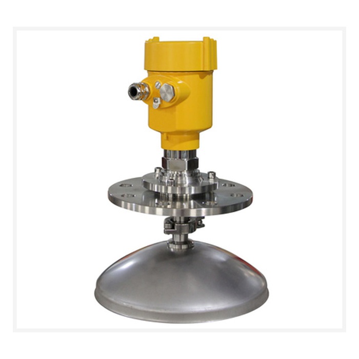
Lower-frequency radar still has important applications despite the widespread use of 80GHz technology. In processes with persistent foam, heavy condensation, unusual gas-phase conditions or selected low-dielectric media, it may be useful to compare lower-frequency non-contact radar, 80GHz radar and guided wave radar.
The correct engineering principle is therefore not “higher frequency is always better,” but rather to select the radar technology according to medium reflectivity, foam, condensation, measuring range and installation conditions.
8. Common Installation Methods for Non-Contact Radar
Non-contact radar transmitters are normally installed from the top of the vessel, tank or silo using a threaded connection, flange, mounting bracket or another suitable process connection. The antenna should have a clear measurement path and should generally face the average material surface as directly as possible.
Avoid Filling Streams
Do not aim the radar directly at falling solids, incoming liquid streams or strong jets.
Avoid Large Internal Obstacles
Where possible, avoid agitators, structural beams, ladders, heating coils and internal piping.
Consider Distance from the Vessel Wall
Do not mount the radar unnecessarily close to the wall. The correct distance depends on beam angle and the product installation instructions.
Check Nozzle Dimensions
A long or narrow nozzle can generate additional reflections and should comply with the permitted dimensions of the selected model.
9. Must the Flange Orientation Mark Always Point Toward the Tank Wall?
No. Some radar transmitters have an orientation mark on the flange, antenna or housing, and the manufacturer may specify a particular direction relative to the vessel wall, bypass opening or internal structure. However, this requirement depends on antenna design, polarization and the specific instrument.
If the product includes an orientation mark, it should be installed according to the instructions for that exact model rather than applying one universal “point toward the wall” rule to all radar transmitters.
10. How Should Radar Be Installed in a Bulk-Solid Silo?
The surface of bulk solids is usually not horizontal and may form an angle of repose. Filling can also create dust and continuously changing material geometry. For this reason, the radar should not normally be installed directly above the filling stream.
The installation point should provide a representative average level and a stable echo. In tall or complex silos, an adjustable flange or another angle-adjustment arrangement may be used where supported by the product so that the radar beam is directed more effectively toward the target surface.
If the echo is affected by walls, support beams or other fixed structures, false-echo suppression can be used to reduce the effect of those stationary reflections.
11. What Is False-Echo Suppression?
Radar signals can be reflected not only by the material surface but also by vessel walls, structural beams, pipes, agitators and other internal objects. These fixed reflections may be interpreted incorrectly as the process level.
Modern radar level transmitters often provide false-echo suppression or echo-learning functions. These functions identify and store the positions or characteristics of fixed reflections so that the instrument can reduce their influence on the actual level measurement.
False-echo suppression is a commissioning tool, not a substitute for correct installation. Obstacles that can be avoided through better sensor positioning should first be addressed by the installation design.
12. How Is Guided Wave Radar Installed?
Guided wave radar uses a rod or cable to guide the radar pulse, so its installation requirements differ from those of non-contact radar. The rod or cable should generally remain vertical and should not contact the vessel wall, internal structures or agitators.
Flexible cable probes in deep vessels may also require consideration of movement and bottom anchoring. Guided wave radar can be useful for selected foam conditions, low-dielectric media, interface measurement and bypass applications, but sticky or scaling products may build up on the probe and increase maintenance requirements.
13. What Information Should Be Confirmed Before Radar Selection and Installation?
| Selection / Installation Item | Information to Confirm |
|---|---|
| Process Medium | Liquid, slurry, powder, granules or bulk solids |
| Dielectric Properties | Whether the medium has low reflectivity or a low dielectric constant |
| Measuring Distance | Maximum distance from the radar installation point to the lowest expected level |
| Process Temperature | Normal, minimum and maximum operating temperature |
| Process Pressure | Atmospheric, positive pressure or vacuum, including maximum design pressure |
| Process Conditions | Foam, vapor, condensation, dust, agitation, buildup and other conditions |
| Vessel Geometry | Tank diameter, height, nozzle, beams, coils, agitators and filling position |
| Installation Method | Thread, flange, bracket, bypass chamber or guided-wave probe |
| Output Interface | 4–20mA, HART, RS485 Modbus RTU or other required interface |
FAQ
Q1: Is high-frequency radar always better than lower-frequency radar?
A1: No. High-frequency radar provides advantages such as a narrow beam and compact antenna, but some foam, heavy-condensation or special-medium applications may be better suited to lower-frequency radar or guided wave radar.
Q2: Why is 80GHz radar suitable for small tanks?
A2: With the same or similar antenna size, 80GHz radar can usually generate a narrower beam and use a smaller antenna, making it easier to avoid vessel walls and internal structures.
Q3: Does lower-frequency radar have a longer or shorter wavelength?
A3: A longer wavelength. Lower frequency means longer wavelength, while higher frequency means shorter wavelength.
Q4: Is radar level measurement affected by temperature and pressure?
A4: Electromagnetic-wave propagation is generally not strongly affected by normal changes in air temperature or pressure, but the instrument itself still has specified mechanical, process-seal and electronics temperature and pressure limits.
Q5: Can radar measure low-dielectric media?
A5: Yes, but lower dielectric constant generally means weaker reflection. A radar with suitable dynamic range, frequency and antenna design should be selected according to the process medium.
Q6: Can a radar level transmitter be installed on a long nozzle?
A6: Yes, but the nozzle diameter and length must comply with the requirements of the specific model. A nozzle that is too long or too narrow may create additional reflections, reduce the useful echo or generate interference.
Q7: Should an 80GHz radar always be used for bulk-solid silos?
A7: 80GHz narrow-beam radar is very suitable for many complex silos, but dust, measuring range, material-surface shape and reflectivity should still be considered during selection.
Q8: What is the main difference between guided wave radar and non-contact radar?
A8: Non-contact radar transmits electromagnetic waves through free space toward the material surface, while guided wave radar directs the signal along a rod or cable and therefore uses a contact measurement structure.
Conclusion
Radar level transmitters provide non-contact measurement, broad medium compatibility, operation in vacuum and demanding temperature or pressure conditions, and convenient integration with industrial automation systems. However, actual performance is still influenced by medium reflectivity, foam, condensation, antenna buildup, vessel geometry and sensor position.
The main advantages of high-frequency radar are shorter wavelength, narrower beam and a smaller antenna, making it particularly useful for small vessels, complex tanks and bulk-solid silos. Lower-frequency radar still has value in selected foam, condensation and special-medium applications, while guided wave radar is useful for certain low-dielectric, interface, foam and bypass-chamber applications.
METRAVON radar level measurement products should be selected according to process medium, measuring range, dielectric properties, process temperature, process pressure, foam, vapor, dust, vessel geometry and required output interface. Correct selection and installation are generally more important than simply choosing the highest available radar frequency.
