


 Chinese
 Spanish
 Russian
 Portuguese
 French
 German
 Indonesian
 Thai
Thai Vietnamese
 Arabic
 Italian
 Turkish
 Polish
 Japanese

Ultrasonic level transmitters calculate liquid or bulk-solid level by transmitting acoustic pulses toward the material surface and measuring the return time of the reflected echo. The technology provides continuous non-contact measurement, but its actual performance depends on more than the transducer itself. Temperature, gas composition, steam, condensation, surface turbulence and installation geometry can all influence acoustic propagation and echo quality.
For high-temperature, pressurized or rapidly changing processes, ultrasonic level measurement requires careful consideration of transducer materials, process-temperature rating, allowable process pressure, temperature compensation, echo processing and sensor position. METRAVON ultrasonic level measurement solutions can be configured with industrial outputs such as 4–20mA and RS485 Modbus RTU for integration with PLCs, RTUs, DCS, SCADA and remote monitoring systems.
1. How Does High Temperature Affect Ultrasonic Level Measurement?
The speed of sound in air changes with temperature. Near 0°C, the speed of sound is approximately 331 m/s and increases by roughly 0.6 m/s for every 1°C increase in temperature. If an ultrasonic instrument calculates distance using a fixed sound velocity, significant temperature variation will directly create a level-measurement error.
Industrial ultrasonic level instruments therefore commonly use temperature sensing and automatic compensation. The measured temperature near the transducer is used to correct the sound-velocity calculation. Standard industrial sensors are generally intended for moderate process temperatures, while specialized high-temperature transducers can extend the operating range through suitable materials, separated electronics and thermal-isolation design.
Some industrial ultrasonic sensors can operate above 100°C, but the maximum temperature is highly model-dependent. A high temperature rating must therefore be confirmed from the specific product datasheet rather than treated as a universal capability of ultrasonic technology.
2. Why Are Separate Transducers and Electronics Used in High-Temperature Applications?
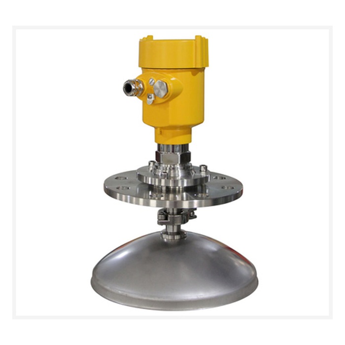
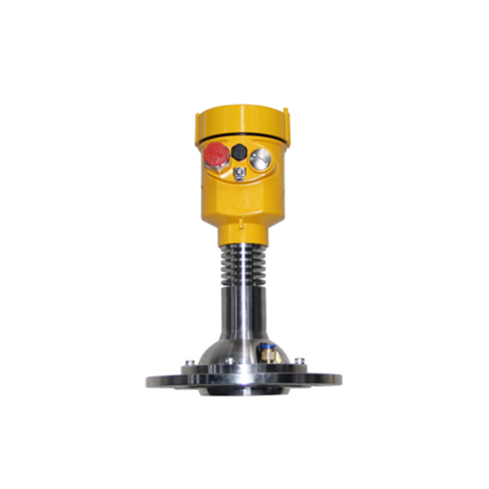
In hot tanks, silos and process vessels, the ultrasonic transducer may need to be installed close to the process while the display, communication and signal-processing electronics should remain in a cooler location. A split-type design allows the sensor to be mounted at the measurement point and the electronic unit to be installed where ambient conditions are more suitable.
The transducer and controller are connected by a dedicated cable. Standard and maximum cable lengths depend on the instrument design. Long cable runs should also be evaluated for signal integrity, electromagnetic interference, grounding and shielding requirements rather than assuming one universal maximum distance.
High-temperature applications may also create deposits, carbonized material or condensation on the transducer surface. Periodic inspection and cleaning may therefore be required to maintain acoustic transmission and echo sensitivity.
3. What Are the Process-Pressure Limitations of Ultrasonic Level Measurement?
Ultrasonic level measurement is not normally considered a primary technology for very high-pressure vessels. The allowable process pressure is first limited by the mechanical design of the transducer, process connection, seals and enclosure. The maximum pressure must therefore be confirmed for the specific model.
It is also inaccurate to assume that increasing pressure simply increases gas density and therefore changes the speed of sound proportionally. For ultrasonic time-of-flight measurement, temperature and gas composition are generally more direct factors affecting acoustic velocity. In real process vessels, pressure may also be accompanied by changes in vapor concentration, gas composition, condensation and acoustic attenuation.
For this reason, applications in pressurized vessels should evaluate process-pressure rating, process temperature, gas composition, steam and condensation together. Some industrial ultrasonic instruments are designed for process pressures of several bar, but the permitted range differs substantially between product families.
For genuinely high-pressure or combined high-temperature/high-pressure processes, radar or guided-wave radar should normally be evaluated as alternative measurement technologies.
4. Sealing, Enclosure Protection and Hazardous Areas
Within the specified pressure range, the process connection should use an appropriate threaded or flanged arrangement and compatible seals to prevent process gas or liquid leakage. Seal materials should be selected according to process temperature, chemical compatibility and pressure requirements.
On some split-type ultrasonic instruments, the sensor may provide IP68 protection while the remote electronic unit is rated IP65 or IP66. An IP rating describes protection against dust and water ingress; it does not define process-pressure capability and does not replace hazardous-area certification.
Where the instrument is installed in an explosive atmosphere, the specific device version must carry the appropriate certification for the hazardous-area classification, gas or dust group and applicable temperature class.
5. How Are Rapidly Changing or Turbulent Surfaces Measured?
Rapid filling, discharge, turbulence, agitation and continuously changing bulk-solid surfaces can cause the location and amplitude of the ultrasonic echo to change quickly. If the instrument response is set too fast, the output may fluctuate unnecessarily. If excessive damping is used, the measured value may respond too slowly to a real process change.
Industrial ultrasonic instruments can use echo recognition, digital filtering, damping, dynamic thresholds and false-echo suppression to balance response speed and measurement stability. These parameters should be matched to the actual process dynamics rather than simply applying maximum filtering.
Avoid Filling Streams
Prevent incoming liquid or falling material from crossing the primary acoustic path.
Avoid Agitators
Reduce unwanted echoes from blades, vortexes and moving mechanical structures.
Set Appropriate Damping
Balance response speed and output stability according to process dynamics.
Suppress False Echoes
Reduce reflections from fixed pipes, beams, vessel walls and other structures.
6. Beam Angle, Blocking Distance and Sensor Position
Ultrasonic transducers have a defined acoustic beam. Typical industrial beam angles may be approximately 5°–12°, depending on transducer frequency, diameter and measurement range. A narrower beam can reduce the probability of vessel walls and internal structures entering the measurement path, but it cannot compensate for incorrect sensor positioning.
The transducer should normally face the average material surface as directly as possible and should be positioned away from filling points, agitators, ladders, structural beams, pipes and major wall reflections. Bulk-solid installations should also consider the material angle of repose and changing surface geometry during filling.
Every ultrasonic transducer also has a blocking distance or dead zone near the sensor where reliable measurement is not possible. Depending on the transducer and range, typical values may be approximately 0.25–1.2 m or greater. The highest expected level must remain outside this zone with an appropriate engineering margin.
7. Long-Term Stability and Maintenance
Long-term measurement stability begins with correct application design. Maximum measuring distance, highest level, process medium, process temperature, process pressure, vapor conditions, gas composition, surface dynamics and available installation space should all be defined before the sensor is selected.
Mechanical mounting should remain rigid and stable. Power, signal and high-voltage cables should be routed according to industrial EMC practice. RS485 communication networks should use suitable twisted-pair cable and, where required, appropriate shielding, grounding, termination and surge protection.
Routine inspection should include the transducer face, process seals, cable, process connection and mounting structure. Dust, deposits, condensation or carbonized material should be removed using a cleaning method compatible with the sensor material. Maintenance frequency should be determined by actual contamination conditions rather than a fixed interval.
8. Signal Outputs and Automation-System Integration
Depending on the selected model, METRAVON ultrasonic level measurement products can provide 4–20mA, RS485 Modbus RTU, relay or other project-specific output options.
A 4–20mA output is suitable for PLC, DCS and conventional analog control systems. RS485 Modbus RTU supports digital data acquisition and can be connected to PLCs, RTUs, data loggers and industrial gateways for further integration with SCADA, Ethernet, cellular or IoT monitoring systems.
For dynamic processes, damping and response time can be configured at the instrument level, while additional filtering, alarms and trend analysis can also be implemented in the PLC or SCADA system.
9. Typical Technical Parameters
The following values represent typical engineering ranges found in industrial ultrasonic level measurement and are intended for preliminary project selection. Actual METRAVON range, temperature, pressure, enclosure, output and material specifications should be confirmed from the datasheet of the selected model.
| Parameter | Typical Value / Range | Notes |
|---|---|---|
| Measurement Range | Liquid ranges may include approximately 0.3–15 m, 30 m or 50 m configurations | Effective solid range depends on reflectivity, dust and surface geometry |
| Measurement Accuracy | Typical ±0.25% to ±0.5% FS or millimeter-level error range | Model and test-condition dependent |
| Resolution | Typically 1–3 mm or range-dependent | Depends on model and signal processing |
| Blocking Distance | Typically approximately 0.25–1.2 m | Varies with transducer and measuring range |
| Power Supply | Common options include 12–24 VDC, 18–30 VDC or AC-powered configurations | Depends on two-wire/four-wire design and model |
| Output | 4–20mA, RS485 Modbus RTU; relays or other options on selected models | For PLC, DCS and RTU integration |
| Power Consumption | Low-power configurations available depending on model | Depends on supply and output design |
| Protection Rating | Selected probes may reach IP68; electronic units may use IP65/IP66 | Confirm by model and construction |
| Process Temperature | Standard models commonly around -20 to +80°C; high-temperature versions model-dependent | Some industrial ultrasonic sensors operate above 100°C |
| Process Pressure | Atmospheric to limited positive-pressure service | Maximum allowable pressure must be confirmed by model |
| Beam Angle | Typically approximately 5°–12° | Depends on frequency, transducer and range |
| Communication | RS485 Modbus RTU and other model-dependent interfaces | For automation-system integration |
| Cable | PVC, PUR or other industrial cable jackets | Length and material depend on model and installation |
| Sensor / Housing Material | ABS, PVC, PVDF, PTFE, engineering plastics or metallic materials | Selected according to temperature and chemical compatibility |
FAQ
Q1: What is the maximum process temperature for an ultrasonic level transmitter?
A1: Standard industrial ultrasonic instruments are generally designed for moderate process temperatures, commonly around 80°C. Specialized high-temperature transducers can exceed 100°C, but the maximum permitted temperature must be confirmed for the specific model.
Q2: Can ultrasonic level transmitters be used on high-pressure vessels?
A2: Ultrasonic measurement is not normally the first choice for very high-pressure applications. Some instruments can operate under limited positive pressure, but the maximum rating depends on the transducer, process connection and sealing design. Radar or guided-wave radar should be evaluated for genuinely high-pressure processes.
Q3: Does increasing pressure directly change the speed of sound?
A3: The relationship should not be simplified in that way. Temperature and gas composition are generally important factors affecting acoustic velocity. Pressurized vessels also require evaluation of vapor composition, condensation and the mechanical pressure rating of the instrument.
Q4: How can rapidly changing or turbulent surfaces be measured?
A4: Stability can be improved through correct sensor positioning, digital filtering, damping, dynamic echo recognition and false-echo suppression. Response settings should match the actual speed of the process.
Q5: Why is a split-type ultrasonic instrument useful at high temperature?
A5: The transducer can be installed near the process while the electronic unit is located in a cooler and more accessible environment, reducing thermal exposure of electronic components.
Q6: Does IP68 mean an ultrasonic sensor is suitable for high process pressure?
A6: No. IP68 describes dust and water ingress protection. Process-pressure rating is a separate mechanical specification and must be confirmed from the product datasheet.
Q7: How should measurement range and blocking distance be selected?
A7: The measuring range should cover the maximum distance from the sensor to the lowest expected level while keeping the highest level outside the specified blocking distance. An additional engineering margin should also be included.
Q8: Should a dynamic process use faster response or stronger filtering?
A8: The settings should be balanced according to the control objective. Fast processes require shorter response times, while storage monitoring can often use greater damping. Excessive filtering can delay the indication of real process changes.
Q9: Can ultrasonic level transmitters be integrated with PLC and remote monitoring systems?
A9: Yes. A 4–20mA output can connect to PLC or DCS analog inputs, while RS485 Modbus RTU can connect to PLCs, RTUs, data loggers and industrial gateways for Ethernet, cellular or other remote communications.
Q10: What information is required for ultrasonic level transmitter selection?
A10: Important information includes process medium, minimum and maximum level, process temperature, process pressure, vapor or gas conditions, surface dynamics, installation geometry, available power and required output or communication interface.
Conclusion
The application limits of ultrasonic level measurement in high-temperature, pressurized and dynamic processes depend on transducer temperature rating, allowable process pressure, gas conditions, echo quality and installation geometry. Temperature effects can be reduced through compensation, while pressurized applications require separate verification of mechanical pressure rating, gas composition, vapor conditions and process sealing.
METRAVON ultrasonic level measurement products can be configured with suitable measuring ranges, enclosure options, materials and interfaces such as 4–20mA and RS485 Modbus RTU for integration with PLCs, RTUs, DCS, SCADA and remote monitoring systems. Correct selection, installation, filtering and periodic maintenance can improve long-term measurement stability and provide a compatible platform for future automation-system expansion.
