


 Chinese
 Spanish
 Russian
 Portuguese
 French
 German
 Indonesian
 Thai
Thai Vietnamese
 Arabic
 Italian
 Turkish
 Polish
 Japanese

Ultrasonic level transmitters use high-frequency sound pulses and echo travel time to provide non-contact level measurement. They are widely applied in water treatment, industrial tanks, selected bulk-solid silos, open channels and process-control systems. Measurement performance depends not only on the instrument itself but also on air temperature, steam, condensation, dust, surface conditions and installation geometry.
METRAVON ultrasonic level transmitters can be configured with temperature compensation, echo-processing functions, suitable enclosure protection and industrial outputs such as 4–20mA and RS485 Modbus RTU. These interfaces allow integration with PLCs, RTUs, DCS, SCADA and remote data-acquisition systems. For long-term operation, correct selection, installation and periodic inspection are often as important as the nominal instrument accuracy.
1. How Temperature and Climate Affect Ultrasonic Measurement
An ultrasonic pulse travels through the gas space between the sensor and the product surface. The speed of sound in air is approximately 331 m/s near 0°C and increases by roughly 0.6 m/s for each 1°C rise in temperature. Without compensation, substantial temperature variation can therefore introduce a direct distance-measurement error.
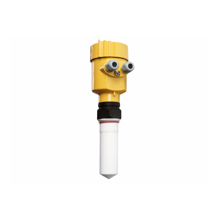
Applicable METRAVON models can use temperature sensing and automatic compensation to correct the sound-velocity calculation. Typical configurations may provide probe operating temperatures of approximately -20 to +80°C and electronic-unit temperatures of approximately -20 to +60°C, although the exact limits depend on the selected model. Outdoor water applications, tanks and installations with large day-to-night temperature changes should therefore be evaluated against the specified temperature range.
2. Steam, Condensation and High-Humidity Environments
Normal atmospheric humidity is not usually the main limitation for ultrasonic level measurement. However, significant steam, condensation, strong temperature gradients or water accumulation on the transducer surface can change sound propagation and reflection conditions, leading to attenuation or unstable echoes.
Measurement stability can be improved through appropriate range selection, echo thresholds, false-echo suppression and correct installation. Where the electronics should not be installed directly at the measurement point, a separate sensor and transmitter arrangement may be used. Some split-type models allow extended sensor cables, but long cable runs must be evaluated against the specified cable limit, signal integrity and electromagnetic compatibility requirements.
3. Dust, Foam and Bulk-Solid Measurement
Dust, foam and irregular solid surfaces can attenuate ultrasonic energy. A liquid normally provides a relatively stable reflective surface, while powders, granules and bulk solids may create sloped surfaces, scattering and airborne dust. As a result, the effective range for solids is generally shorter than the nominal liquid range of the same transducer.
In some bulk-solid applications, the usable range may be around 50% of the liquid range, but this is not a fixed engineering rule. Actual performance depends on particle size, surface angle, dust concentration, acoustic absorption and sensor location. Protective covers may also be used where appropriate to reduce contamination of the transducer and long-term exposure to rain, ultraviolet radiation or airborne particles.
4. Corrosive Environments and Material Selection
For chemical or corrosive applications, material compatibility must be considered in addition to echo performance. Depending on the model and project requirements, sensor and enclosure materials may include ABS, PVC, PVDF, PTFE, engineering plastics or aluminum alloy.
Where corrosive gases, chemical splashes or long-term outdoor exposure are expected, materials should be selected according to chemical composition, concentration and operating temperature. Hazardous-area applications require an appropriately certified explosion-protected version; a standard enclosure IP rating alone does not indicate suitability for an explosive atmosphere.
5. Protection Rating, Process Pressure and Outdoor Installation
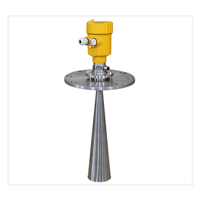
Ultrasonic level transmitters are commonly used in atmospheric or near-atmospheric tanks, basins and silos. Some industrial models may tolerate limited positive pressure, for example around 0.1 MPa, but the actual allowable process pressure must always be confirmed from the specific product datasheet.
For split-type products, certain probes may provide IP68 protection while the electronic transmitter may use an IP65 or IP66 enclosure. An IP rating describes resistance to dust and water ingress; it should not automatically be interpreted as approval for permanent immersion, high-pressure washdown or hazardous-area service.
6. Correct Installation Is Essential for Long-Term Stability
Sensor position has a major influence on echo quality. The transducer should normally face the average material surface as directly as possible and should be located away from filling streams, agitators, heating coils, ladders, structural beams and vessel walls that may generate unwanted echoes. For bulk solids, the filling pattern and expected angle of repose should also be considered.
After an ultrasonic transducer emits a pulse, there is a short region in which reliable echoes cannot be detected. This is normally called the blocking distance or dead zone. Depending on the model and measuring range, typical blocking distances may be approximately 0.25 to 1.2 m or more. The highest expected material level must therefore remain outside this zone.
Power, communication and high-voltage cables should be routed according to industrial EMC practice. RS485 networks should use suitable twisted-pair cabling and, where required, shielding, grounding, termination and surge protection appropriate to the cable length and electrical environment.
7. Cleaning and Periodic Maintenance
Ultrasonic level measurement has no mechanical moving parts in contact with the process medium, so routine maintenance requirements are generally limited. However, dust, condensation, scale or other contamination can accumulate on the transducer surface and reduce transmitted or received acoustic energy.
Inspection intervals should be based on actual site conditions. In applications with visible contamination, an inspection cycle of approximately one to six months may be appropriate. The transducer surface, cable, seals, mounting structure and electrical connections should be checked. Cleaning should normally use a soft cloth, clean water or a cleaner confirmed as compatible with the sensor material; abrasive tools and unverified aggressive solvents should be avoided.
8. Echo Settings, Temperature Compensation and Signal Outputs
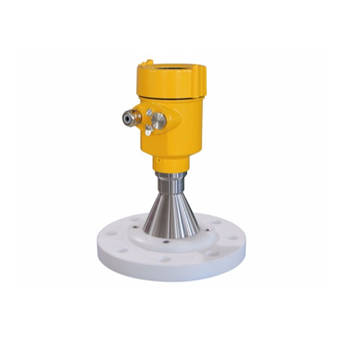
After installation, the instrument should be configured for the actual vessel or silo. Important settings can include zero and full-scale points, blocking distance, response time and echo-recognition parameters. Where fixed structures create interference, false-echo suppression can be used to reduce the effect of known stationary reflections. Temperature compensation should also be verified across the expected operating range.
Depending on the selected model, output options can include 4–20mA, RS485 Modbus RTU and relay alarms, while HART may be available on selected versions. A 4–20mA output can represent level, distance or ullage, while RS485 Modbus RTU can provide digital process values and status information for integration with PLCs, RTUs, DCS, SCADA systems and industrial gateways.
Some models also allow a defined response during measurement failure, such as holding the last valid value or switching to a preset fault output. The exact fault behavior and current value should be configured according to the instrument manual and control-system requirements.
9. Typical Technical Parameters
The following values represent typical engineering configurations available across industrial ultrasonic level instruments and are intended for preliminary selection. GB/T 38615-2020 is the Chinese national general specification for ultrasonic level meters. Actual METRAVON specifications, applicable standards and certifications should be confirmed from the datasheet of the selected model.
| Parameter | Typical Value / Range | Notes |
|---|---|---|
| Measurement Range | Liquid ranges may include approximately 0.3–15 m, 30 m and 50 m configurations | Solid range depends on reflection, dust and surface conditions |
| Measurement Accuracy | Typical ±0.25% to ±0.5% FS or millimeter-level error range | Depends on model and test conditions |
| Resolution | Typically 1–3 mm or range-dependent | Depends on signal processing and model |
| Blocking Distance | Typically approximately 0.25–1.2 m | Varies with range and transducer design |
| Power Supply | 12–24 VDC, 18–30 VDC or AC-powered configurations | Depends on two-wire/four-wire design and model |
| Output Signal | 4–20mA, RS485 Modbus RTU; HART or relay available on selected models | For PLC, DCS and RTU integration |
| Power Consumption | Typically approximately 1.5–3 W or less | Depends on model and supply configuration |
| Protection Rating | Selected probes may reach IP68; electronic units may use IP65/IP66 | Depends on product construction |
| Operating Temperature | Probe typically -20 to +80°C; electronics typically -20 to +60°C | Confirm for selected model |
| Process Pressure | Atmospheric; selected models may tolerate limited positive pressure | Confirm maximum pressure by model |
| Beam Angle | Typically approximately 5°–12° | Depends on transducer frequency and range |
| Communication | Modbus RTU; HART available on selected models | Supports industrial system integration |
| Cable | PVC, PUR or other industrial cable jackets | Length and material depend on model and installation |
| Sensor / Housing Material | ABS, PVC, PVDF, PTFE, engineering plastics or aluminum alloy | Selected according to corrosion and environmental conditions |
FAQ
Q1: How does temperature affect ultrasonic level measurement?
A1: The speed of sound in air changes with temperature, so temperature variation changes the relationship between echo travel time and distance. Models with temperature compensation correct the sound-velocity calculation to reduce this error.
Q2: Can ultrasonic level transmitters operate in dusty or steamy environments?
A2: Suitability depends on dust concentration, steam level, measurement range and available echo strength. Echo processing, correct installation and suitable protective structures can improve reliability, but severe dust or continuous heavy steam can significantly reduce usable range.
Q3: What are the most important installation requirements?
A3: The sensor should face the average material surface, avoid filling streams and major internal obstructions, remain outside the specified blocking distance and be mounted on a mechanically stable structure.
Q4: What routine maintenance is required?
A4: Inspect the transducer surface, cable, seals, mounting structure and electrical connections. Where dust, condensation or scale is present, establish a cleaning interval according to the actual contamination rate.
Q5: Which outputs and communication interfaces are available?
A5: Depending on the model, outputs can include 4–20mA and RS485 Modbus RTU, while selected versions may also provide HART or relay outputs for integration with PLCs, RTUs, DCS, SCADA or industrial gateways.
Q6: Does IP68 mean the entire instrument can remain permanently submerged?
A6: Not necessarily. In a split-type instrument, the probe may be IP68 while the electronic unit is IP65 or IP66. The permitted exposure conditions should be confirmed separately for each component.
Q7: How should the measurement range be selected?
A7: Select a range based on the maximum distance from the sensor to the lowest expected level, while allowing for blocking distance, engineering margin and echo strength. Bulk solids also require consideration of dust, surface angle and scattering.
Q8: What should be checked if the reading becomes unstable over time?
A8: Check transducer contamination, mounting stability, fixed obstacles, temperature variation, false echoes, signal strength, power supply and communication wiring. Echo learning or parameter verification may be required.
Q9: Can ultrasonic level transmitters be used for remote monitoring?
A9: Yes. A 4–20mA signal can be connected to a remote PLC or RTU, while RS485 Modbus RTU can provide digital data to an industrial gateway for Ethernet, cellular or other remote communication.
Q10: What is the main difference between liquid and bulk-solid measurement?
A10: Liquids generally provide a relatively stable reflecting surface. Bulk solids may form sloped surfaces, generate scattering and produce dust, so they normally require more measurement margin and more careful sensor positioning.
Conclusion
Long-term ultrasonic level measurement stability depends on temperature compensation, echo quality, installation position, enclosure protection and maintenance condition. Temperature variation, steam, condensation, dust, foam and irregular product surfaces can all influence sound propagation or reflection, so range and sensor configuration should be selected according to actual process conditions.
METRAVON ultrasonic level transmitters can be configured with 4–20mA, RS485 Modbus RTU and other optional interfaces for integration with PLCs, RTUs, DCS, SCADA and remote monitoring systems. Correct selection, installation and periodic inspection help maintain stable level data while providing a compatible and scalable interface for future automation-system expansion.
