


 Chinese
 Spanish
 Russian
 Portuguese
 French
 German
 Indonesian
 Thai
Thai Vietnamese
 Arabic
 Italian
 Turkish
 Polish
 Japanese

METRAVON Ultrasonic Level Transmitter Alarm, Data Logging and System Integration Guide
Ultrasonic level transmitters calculate liquid or bulk-solid level by transmitting acoustic pulses toward the material surface and measuring echo travel time. In addition to continuous level measurement, industrial systems can use alarm thresholds, relay outputs, 4–20mA signals and digital communication to implement high/low level alarms, pump-control logic, historical data logging and remote monitoring.
The level transmitter itself is normally focused on real-time measurement and signal output. Complete historical databases, trend charts, SMS or email notifications, user permissions and cloud data management are usually implemented by external PLCs, RTUs, SCADA systems, data loggers or IoT platforms. The instrument and control system should therefore be designed as one integrated monitoring architecture.
1. How Does an Ultrasonic Level Transmitter Provide Automatic Alarms?
Automatic alarm functions compare the measured level with configured thresholds. Depending on the instrument and control system, the application may use high, low, high-high or low-low alarm points. Hysteresis and time delay can also be applied to prevent unstable switching when the measured surface fluctuates near a threshold.
Alarm logic can be implemented inside an ultrasonic transmitter equipped with relay outputs, or it can be performed in a PLC, DCS or other external controller. For complex interlocks, multi-stage alarm management and remote notifications, implementing the logic at the control-system level generally provides greater flexibility.
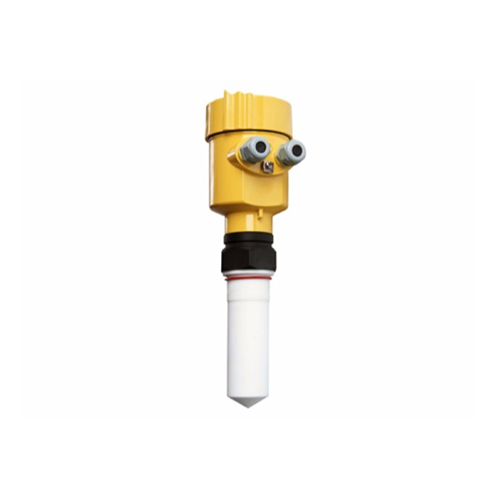
2. Three Common Alarm Output Methods
Relay Alarm Output
Selected models can provide one or more relay outputs for high/low alarms, interlocks or control signals. Relay type, quantity and contact rating depend on the specific model.
4–20mA Alarm Logic
The continuous analog signal is connected to a PLC or DCS analog input, and the control system generates alarms according to the calculated level.
Digital Communication Alarm
RS485 Modbus RTU can transmit level, distance and supported device-status data to a PLC, RTU or SCADA system for multi-stage alarm and historical event management.
Instrument relays are suitable for control signaling or loads within their specified contact rating. Large pumps, motors or other high-power and inductive loads should normally be controlled through an interposing relay, contactor or dedicated motor-control circuit rather than directly from the level transmitter relay.
3. Alarm Thresholds, Hysteresis and Time Delay
A single fixed threshold can cause frequent switching when the process level fluctuates around the alarm point. For example, if a high-level alarm is configured at 8.00 m and the surface repeatedly moves between 7.99 m and 8.01 m, the alarm output may switch on and off unnecessarily.
Industrial alarm systems therefore commonly use hysteresis and time delay. Hysteresis defines a separate reset point after the alarm has been triggered, while time delay requires the level to remain beyond the threshold for a specified period before the alarm becomes active. Settings should reflect process dynamics and the consequences of the alarm condition.
4. How Is 4–20mA Used for Level Alarms?
A 4–20mA output is normally a continuous process signal rather than a simple alarm contact. For example, a 0–10 m level range can be scaled to 4–20mA. The PLC converts the measured current back into level and then applies high, low or high-high alarm logic.
This architecture allows the control system to use the same signal for continuous display, control and multiple alarm levels. Alarm thresholds can also be changed in the PLC or DCS without modifying the physical configuration of the level instrument.
Some instruments can also provide a defined response when the echo is lost or an internal fault occurs, such as holding the last valid measurement or switching to a preset fault output. The exact fault-current value and behavior depend on the selected model and should be configured according to the instrument manual and control-system requirements.
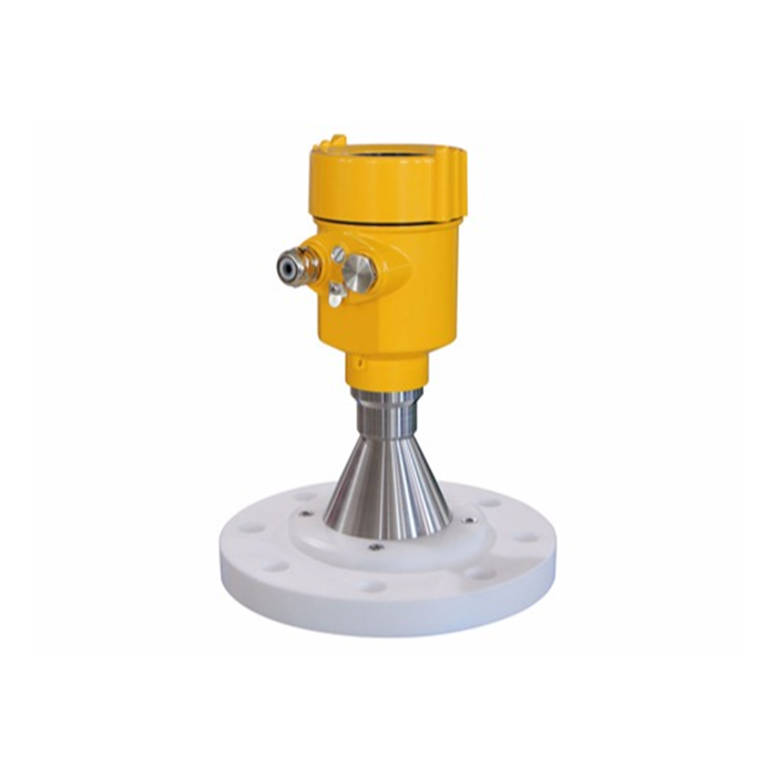
5. How Is RS485 Modbus RTU Used for Alarm and Data Acquisition?
RS485 Modbus RTU is useful in digital level-monitoring systems. A PLC, RTU or data-acquisition unit can periodically read Modbus registers from the ultrasonic level transmitter to obtain level, distance, device status and other parameters supported by the selected model.
Unlike a single 4–20mA channel, Modbus can carry multiple digital values on one communication network. Multiple devices with different addresses can also share one RS485 bus, making the architecture suitable for distributed tanks, reservoirs, pumping stations and environmental monitoring systems.
Alarm decisions can be made inside the transmitter where supported or at the PLC/SCADA level. Centralized software-based alarm management is normally preferable when the project requires alarm priority, acknowledgement, event history or interlocking between several devices.
6. Does the Ultrasonic Level Transmitter Store Historical Data?
This depends on the model. Most industrial ultrasonic level transmitters are designed primarily for real-time measurement and process-signal output and should not automatically be assumed to contain large internal data-storage capacity.
Where long-term historical recording is required, the transmitter can be connected to a PLC, RTU, data logger, SCADA system or industrial IoT gateway. The external system can then add timestamps, store measurements in a database, generate trends and record abnormal events.
Ultrasonic Level Transmitter → PLC / RTU / Data Logger → SCADA / IoT Platform → Historical Data and Alarm Management
7. Remote Monitoring and Historical Data Management
After the level signal reaches an RTU, industrial gateway or control system, it can be transmitted through Ethernet, cellular, Wi-Fi or another communication network to a local server or remote platform. The monitoring platform can provide real-time values, trend charts, alarm history, reports and device-status information.
SMS, email, mobile notifications, user permissions and access control are normally implemented by the SCADA, server or cloud platform rather than by the basic ultrasonic transducer. Encryption, authentication and data-access policies should also be designed at the gateway, network and platform levels.
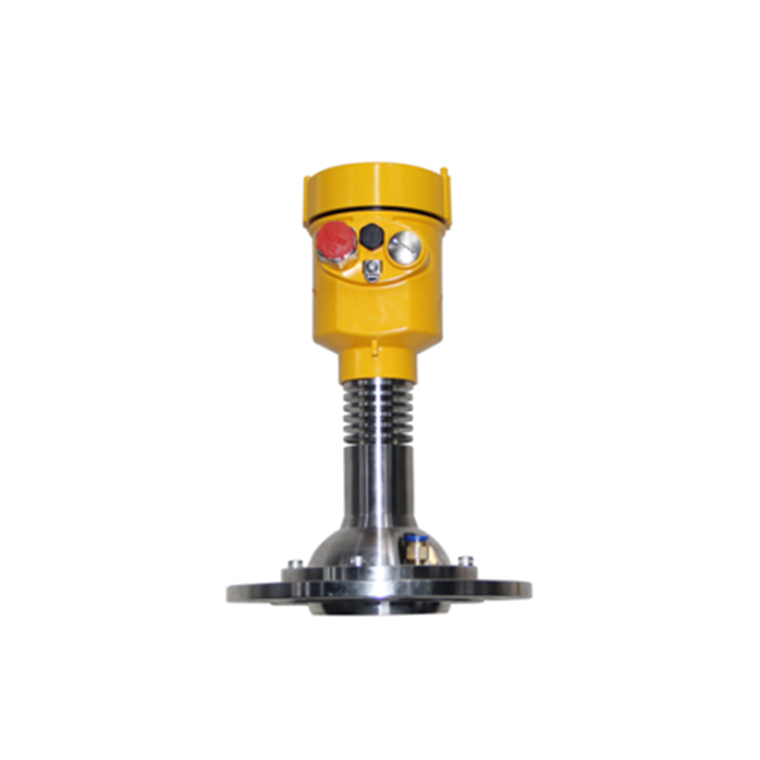
8. Can Temperature and Diagnostic Data Be Logged?
Many ultrasonic level instruments contain an internal temperature sensor for sound-velocity compensation, but this does not mean that every model exposes temperature as a separate process variable. Whether the temperature value can be read through the display, Modbus registers or another interface must be confirmed from the communication protocol of the specific model.
The same principle applies to echo strength, diagnostic status, fault codes and signal quality. If remote diagnostics are required, the selection specification should clearly identify which digital parameters must be accessible to the control system.
9. How Can False Alarms Be Reduced in Difficult Conditions?
Reliable alarms depend on reliable measurement. High temperature, dust, foam, steam, condensation, severe surface movement and internal vessel obstructions can affect ultrasonic echo quality. Alarm software alone cannot compensate for a fundamentally unstable measurement condition.
Correct Installation
Avoid filling streams, agitators, beams and major reflecting structures, and keep the maximum level outside the blocking distance.
Temperature Compensation
Reduces distance errors caused by changes in the speed of sound as ambient temperature changes.
Echo Filtering
Damping, false-echo suppression and suitable response settings can reduce alarms caused by short-term fluctuations.
Periodic Inspection
Check the transducer surface, seals, cables and mounting structure to prevent contamination or mechanical changes from affecting the echo.
10. What Should Be Verified During Long-Term Operation?
Long-term maintenance should include the alarm and communication chain as well as the level measurement itself. Periodic functional testing can confirm that relay outputs, PLC alarms, SCADA records and remote notifications operate correctly when the test condition is introduced.
Important projects should also maintain backups of instrument and PLC configuration, including range, zero point, alarm thresholds, hysteresis, delay, Modbus address, baud rate and communication settings. Configuration changes should be documented so that the system can be restored or investigated after a fault.
11. Typical Technical Parameters
The following values represent typical industrial ultrasonic level measurement configurations for preliminary project selection. Actual METRAVON specifications for measuring range, relays, communication interfaces, temperature, protection rating and materials should be confirmed from the selected model datasheet and communication documentation.
| Parameter | Typical Value / Range | Notes |
|---|---|---|
| Measurement Range | Liquid configurations may include approximately 0.3–15 m, 30 m or 50 m ranges | Effective solid range depends on reflectivity, dust and surface condition |
| Measurement Accuracy | Typical ±0.25% to ±0.5% FS or millimeter-level error range | Depends on model and test conditions |
| Resolution | Typically 1–3 mm or range-dependent | Depends on model and signal processing |
| Blocking Distance | Typically approximately 0.25–1.2 m | Varies by transducer and range |
| Power Supply | Common 12–24 VDC, 18–30 VDC or AC-powered configurations | Depends on model and wiring design |
| Analog Output | 4–20mA | For continuous level and PLC/DCS analog input |
| Digital Communication | RS485 Modbus RTU; other interfaces depending on model | For digital acquisition and system integration |
| Relay Output | One or more relays available on selected models | Quantity, contact type and rating depend on model |
| Relay Contact Rating | Defined by the selected product design | Use an interposing relay or contactor for high-power loads |
| Fault Output | Preset fault behavior available on selected models | Fault current or hold-last-value behavior is model-dependent |
| Protection Rating | Selected probes may reach IP68; electronics may use IP65/IP66 | Confirm by model and construction |
| Process Temperature | Standard industrial models commonly around -20 to +80°C; high-temperature versions model-dependent | Varies with transducer material and construction |
| Process Pressure | Atmospheric to limited positive-pressure service | Maximum pressure must be confirmed by model |
| Beam Angle | Typically approximately 5°–12° | Depends on frequency, transducer and range |
| Data Logging | Normally implemented by PLC, RTU, logger or SCADA | Selected models may provide limited local storage |
| Sensor / Housing Material | ABS, PVC, PVDF, PTFE, engineering plastics or metallic materials | Selected according to process and environmental conditions |
FAQ
Q1: How can an ultrasonic level transmitter provide automatic high and low level alarms?
A1: A model with relay outputs can generate alarm signals internally, or the 4–20mA or RS485 signal can be sent to a PLC, DCS or RTU where the alarm thresholds and interlocks are implemented.
Q2: Can multiple alarm thresholds be configured?
A2: This depends on the instrument and control system. Selected transmitters can provide multiple relay alarm points, while a PLC or SCADA system can normally generate high, low, high-high and low-low alarms from one continuous level signal.
Q3: Is historical data stored inside the level transmitter?
A3: Usually not. Most industrial ultrasonic level transmitters focus on real-time measurement and signal output. Long-term time-series data is normally stored by a PLC, RTU, data logger, SCADA system or IoT platform.
Q4: Can RS485 Modbus RTU be used for remote monitoring?
A4: Yes. Modbus data can be collected by a PLC, RTU or industrial gateway and then transmitted through Ethernet, cellular or another network to a remote platform.
Q5: Can the alarm output indicate instrument faults?
A5: Selected models can provide defined output behavior during echo loss or an internal fault, such as holding the last valid value or switching to a preset fault output. Exact functions depend on the instrument.
Q6: Is the internal temperature value always available to the user?
A6: No. The internal temperature sensor is primarily used for acoustic compensation. Whether the value is available through the display or Modbus registers depends on the specific product protocol.
Q7: Can high temperature, dust or a turbulent surface cause false alarms?
A7: Yes. These conditions can affect echo quality. Correct installation, temperature compensation, filtering, alarm hysteresis and suitable time delays can reduce unnecessary alarms.
Q8: How is the transmitter integrated with a PLC or DCS?
A8: A 4–20mA signal can connect to an analog input module, while RS485 Modbus RTU can connect to a compatible PLC, RTU or gateway. Alarm, trend and historical functions can then be implemented at the PLC, DCS or SCADA level.
Q9: Can the transmitter relay directly start a pump?
A9: Direct switching of high-power pumps or motors is not recommended. The transmitter relay should normally provide a control signal to an interposing relay, contactor or pump-control panel.
Q10: Which alarm and data-management parameters should be confirmed during selection?
A10: Confirm the required number of alarm levels, relay quantity and contact type, 4–20mA or RS485 interface, Modbus register availability, fault-output behavior, data-logging architecture and compatibility with the PLC, DCS or remote platform.
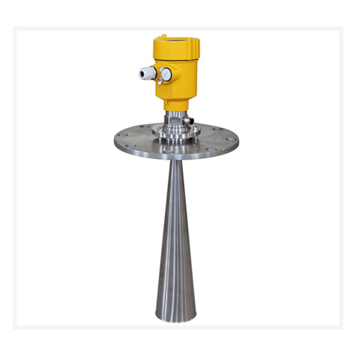
Conclusion
Automatic alarm and data management in an ultrasonic level-monitoring system are normally implemented through a combination of level measurement, relay or process-signal outputs, PLC/RTU control logic and SCADA or remote monitoring software. Relay outputs are useful for local alarm and interlock signaling, 4–20mA is suitable for continuous process control, and RS485 Modbus RTU supports digital data acquisition and future system expansion.
METRAVON ultrasonic level measurement products can be configured with appropriate measuring ranges, output signals, relay functions and communication interfaces for integration with PLCs, RTUs, DCS, SCADA and industrial IoT systems. Correct alarm thresholds, hysteresis, delay and filtering, combined with periodic testing of the measurement, relay and communication chain, help improve long-term alarm reliability and historical-data quality.
