


 Chinese
 Spanish
 Russian
 Portuguese
 French
 German
 Indonesian
 Thai
 Vietnamese
 Arabic
 Italian
 Turkish
 Polish
 Japanese


The centre of a process connection is not necessarily the liquid elevation at which a fork changes state. Tuning fork installation should use the exact device's switching-point reference and mounting orientation. Otherwise a mechanically neat installation can place the actual detection point above or below the intended operating limit.
Locate the required liquid elevation first
Mark the physical detection elevation on the vessel drawing and identify the direction of level movement. Obtain the switching-point information for the offered assembly and the stated liquid conditions. Do not copy an offset from another fork or assume that the tine tip is always the switching point.
Where the duty requires a process action, establish the required detection elevation through the responsible control or protection design. The instrument connection location should follow that requirement, not determine it by convenience.
Tuning fork installation dimensions to approve
| Detail | Check on the offered drawing |
|---|---|
| Orientation | The approved mounting direction and any locating mark used during assembly. |
| Switch reference | How the documented switching point relates to the required vessel elevation. |
| Nozzle | Whether the active fork can contact the intended material and drain as required. |
| Clearance | Separation from walls, internal fittings, deposits and direct incoming flow. |
Check drainage before adding a longer extension
Liquid retained around a recessed fork can delay its return to the uncovered condition. Review nozzle geometry and liquid behaviour using the manufacturer's installation guidance. An extension can change position and loading, so it should be selected as part of the assembly rather than improvised to reach past an unsuitable pocket.
Follow the specified tightening and orientation procedure. Do not loosen a sealed process connection merely to rotate the fork into a preferred position. If correct sealing and orientation cannot both be achieved with the proposed components, resolve the arrangement before commissioning.
A different sensing principle needs its own drawing
The METRAVON MV-SP601 is an RF admittance switch, not a tuning fork. Its rod or cable length positions a sensing arrangement that must be identified on its own drawing. An RF alternative cannot inherit a fork's switching offset or orientation rule.
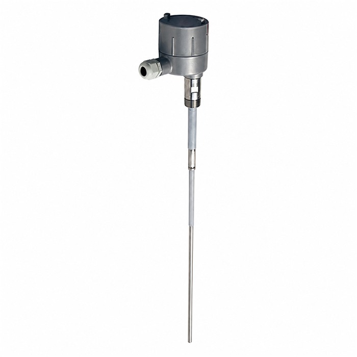
Provide the connection, vessel construction, material and target elevation for a separate assessment. Confirm the output version and receiving logic too; a successful mechanical fit is not proof that the existing circuit will interpret the new switch correctly.
Check liquid suitability and return-to-clear behaviour before approving the mechanical arrangement; a correct mounting position cannot compensate for an unsuitable sensing duty.
Q1. Can the same nozzle be reused for another fork model?
Approve the new assembly's switching-point reference, dimensions, process connection and permitted orientation before reusing the nozzle. Check that the active fork reaches the intended liquid condition and can drain as required. A shared thread or flange does not establish the same detection elevation, and an extension selected for another model does not establish a compatible assembly.
Q2. What should be checked after installation?
Under the approved site procedure, observe the actual covered and cleared transitions and compare the device output with the receiving controller's state. Retain the installed orientation, detection elevation and liquid condition with those observations. If a downstream action is simulated or excluded, record that limit explicitly; a local switch indication alone does not verify the complete alarm or control path.
Summary
Approve the switching position, drainage and connection as one arrangement. Send the vessel section and required detection elevation when considering a documented MV-SP601 alternative.
