


 Chinese
 Spanish
 Russian
 Portuguese
 French
 German
 Indonesian
 Thai
 Vietnamese
 Arabic
 Italian
 Turkish
 Polish
 Japanese


A late high-level alarm does not necessarily mean a slow switch. Material must reach the active sensing area, the instrument must change output, and the controller must act on that change. Assess tuning fork level switch response across the installed sequence before replacing a device or reducing every delay setting.
Define the events that start and stop the timing
Begin with the process requirement. "Alarm within the required time" is incomplete unless it states whether timing starts when the surface reaches a specified elevation or when liquid actually contacts the sensing element. A recessed connection, trapped air or an unsuitable installation can separate those events.
Immersion changes a liquid fork's vibration behaviour, which its electronics interpret according to the particular design and settings. A local indicator, switched output and controller input are different observation points. Check what each indication represents in the relevant instructions.
| Event | What to record | What the interval can reveal |
|---|---|---|
| Process reaches the intended elevation | A safely obtained level reference and its time | Whether the alarm is positioned appropriately for the required action |
| Material contacts the active element | Contact evidence or the approved test's stated limitation | Delay caused by the nozzle, wetting or local liquid access |
| Instrument output changes | The actual output state, not only an operator's screen observation | Instrument response and configured delay after contact |
| Controller accepts the input | Input state and program event | Input filtering, scan timing or programmed persistence |
| Required equipment action occurs | Command, actuator response and relevant process movement | Delay downstream of the sensing instrument |
Use a time reference that can resolve the question
Record the observations on a common time base where practical. If a historian samples less frequently than the delay being investigated, its trend cannot separate the events reliably. Record the observation uncertainty rather than converting a screen-refresh interval into a claimed sensor specification.
Do not assign a catalogue response time to the entire shutdown sequence. Even after a stop command, a valve may still travel or material already in a line may continue entering the vessel. The responsible control and process engineers must evaluate that remaining movement when deciding the available response time.
Tuning fork level switch response: follow the delayed stage
Contact is late, but switching follows promptly. Inspect the mounting and how liquid reaches the element. Lowering a PLC filter does not correct a fork recessed in a pocket that fills after the main vessel. Confirm the active sensing position on the actual assembly drawing.
The output changes promptly, but the PLC event is late. Review the receiving input, any interface device and the program's filtering or persistence logic. Preserve existing settings before testing a change. An electrical simulation can isolate this downstream path, but it bypasses the material-detection step.
Detection is acceptable, but reset is late or inconsistent. Observe drainage, wet film and normal deposits during emptying. Repeat the test with representative residue present. Cleaning the element between every cycle may conceal the condition that causes the plant fault.
Use the approved site test and isolation arrangements. Where real material contact cannot be observed safely, document which parts of the sequence the test covers. Do not raise hazardous liquid or defeat protection to obtain a stopwatch reading.
Assess an RF alternative without transferring the fork's specification
METRAVON MV-SP601 is an RF admittance point-level switch, not a tuning fork. Its coating-rejection circuitry addresses unwanted responses from adhering material; it is not a self-cleaning function and does not establish a particular switching or reset time.
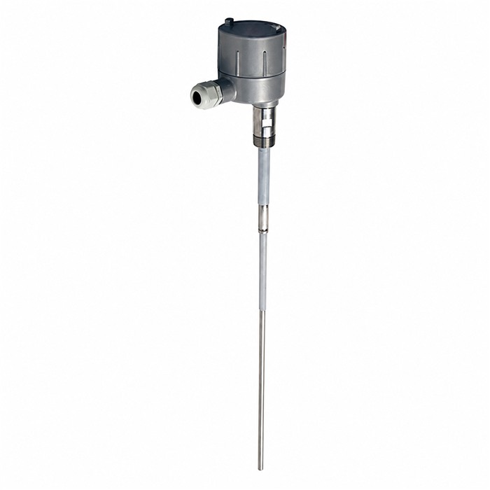
For an alternative assessment, provide the material, sensing elevation, connection, residue condition and required end-to-end action. Identify both the covered-to-alarm and clear-to-reset requirements. Ask the offer to specify the active sensing region, electrical output, power-loss behaviour and applicable response settings for the proposed assembly.
Then compare the offered configuration with the receiving circuit. Matching an alarm height does not prove that probe geometry, contact behaviour or controller interpretation is equivalent to the removed fork. Verify actual detection and the downstream action separately. An ordinary point-level alarm is not an independently approved safety function merely because it responds quickly.
Questions from response tests
Q1. Should every configurable delay be reduced to its minimum?
No. A shorter delay may admit transient splashes or contact chatter into the alarm logic, while excessive filtering may obscure a sustained event. Identify the disturbance and the allowed process response first. After an approved change, retest detection, reset and the receiving logic rather than checking only the local output.
Q2. Does a fast local indicator prove that the equipment stops quickly?
It establishes only when that indication changed. Verify what drives it, then compare the output, controller event, stop command and actual equipment action. A prompt instrument output can coexist with a delayed receiving action or continued material flow.
Q3. What should be supplied when asking METRAVON about a replacement?
Send the existing device identification and drawing, the material and deposit condition, the input circuit, and a timeline showing where the delay occurs. Add the required response and reset conditions. This lets the MV-SP601 assessment address the actual fault without promising that an RF probe duplicates a fork's behaviour.
Summary
Locate the delay before changing the instrument. A useful test distinguishes access to the sensing area, switching, controller processing and final action. Include those observations in an MV-SP601 application enquiry so the proposed probe and output can be checked against the required duty.
