


 Chinese
 Spanish
 Russian
 Portuguese
 French
 German
 Indonesian
 Thai
 Vietnamese
 Arabic
 Italian
 Turkish
 Polish
 Japanese


Radar and ultrasonic site trials often place several instruments on one vessel to compare readings. That arrangement can introduce effects that will not exist in the final installation. Identify which units operate together, their positions and their electrical connections before treating a difference in readings as evidence that one technology is unsuitable.
Do not call every disagreement cross-talk
An ultrasonic transmitter uses acoustic energy and a radar uses electromagnetic energy. Their different measurement principles do not imply direct acoustic cross-talk between that pair. Nevertheless, shared power, wiring, grounding, physical obstruction or different target positions can still complicate the comparison.
When several ultrasonic systems are present, consult their exact documentation for separation or synchronisation requirements. Some systems provide specific coordination arrangements; others differ. Do not assume that an unspecified synchronisation terminal exists, or copy a wiring method from an unrelated controller.
Make radar and ultrasonic site trials interpretable
| Test detail | What to hold or record |
|---|---|
| Geometry | Each sensor position, reference height and view of the surface. |
| Operation | Which instruments were transmitting and which process equipment was running. |
| Electrical path | Supply, receiver and cable arrangement used by each measurement chain. |
| Reference | An independent observation and common time basis for comparing results. |
Use controlled changes, not an uncontrolled demonstration
If permitted by site procedures, compare authorised combinations of instruments while keeping the process as similar as practicable. Never switch off an instrument that performs a required control or protection function merely to simplify the trial. Record the intervention and its timing so a process change is not mistaken for an interference effect.
A single-instrument result and a simultaneous-operation result answer different questions. Repeat a suspected effect where it is safe to do so, and retain the conditions that did not reproduce it. Do not conclude that all instruments of one technology interfere because one installation showed an unexplained discrepancy.
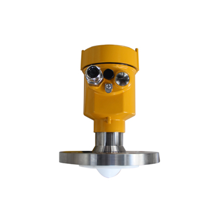
Assess MV-RD12 on its own documented configuration
The METRAVON MV-RD12 is a liquid radar candidate for a suitable comparison. Its catalogue does not establish a universal multi-radar coordination function or interference-free operation in every arrangement. Submit the proposed layout and operating combination where several radars will remain installed.
Also distinguish test wiring from the permanent interface. Different damping, update timing or receiving-system filters can make two valid readings appear inconsistent during a changing level. Compare like quantities at known times before attributing the difference to the sensing principle.
Q1. Does agreement between two sensors prove accuracy?
No. Both can share an incorrect reference, conversion or view of an unintended target. Include an independent check appropriate to the required measurement and its acceptance tolerance.
Q2. Can a temporary side-by-side trial qualify the final installation?
Only for the conditions it actually demonstrates. Reassess changes to position, nozzle, cabling and the number of operating instruments before accepting the permanent arrangement.
Summary
Control the comparison before ranking the instruments. Provide the trial layout, simultaneous-operation record and reference results to support an evidence-based MV-RD12 selection.
