


 Chinese
 Spanish
 Russian
 Portuguese
 French
 German
 Indonesian
 Thai
Thai Vietnamese
 Arabic
 Italian
 Turkish
 Polish
 Japanese

1. Differences in Physical Measurement Mechanisms and Operating Principles for Industrial Level Measurement
In hydraulic engineering, municipal water systems, and industrial process control, continuous level measurement is a core component of automated monitoring and data acquisition systems such as SCADA. Although radar water level meters and ultrasonic water level meters can both provide standard 4–20 mA analog outputs or RS-485 Modbus RTU digital signals, there are fundamental differences in their underlying physical wave transmission mechanisms.
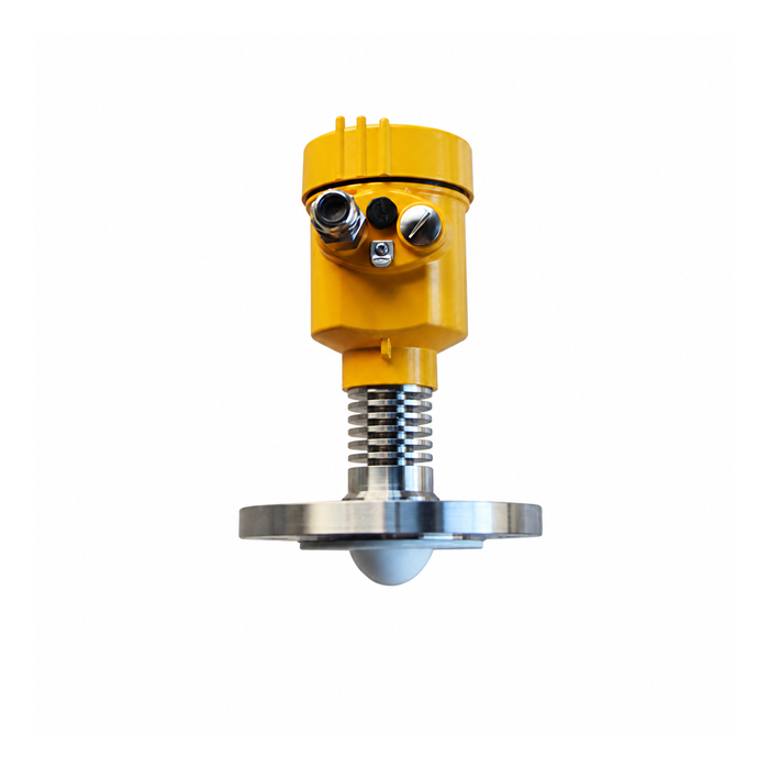
1.1 Radar Water Level Meter: High-Frequency Electromagnetic Wave Transmission Mechanism
Radar water level meters, including non-contact pulse/FMCW radar and guided wave radar (GWR), operate based on electromagnetic wave propagation. The radar antenna transmits high-frequency electromagnetic waves, typically 26 GHz or 80 GHz microwaves, or high-frequency TDR pulses. These electromagnetic waves travel through air or along the measurement path at approximately the speed of light, about 3 × 10⁸ m/s.
When the electromagnetic wave reaches the surface of the measured liquid, part of the wave is reflected because of the discontinuity in dielectric constant between air and the measured medium. The reflected wave is received by the antenna. The system calculates the distance D from the sensor reference plane to the liquid surface by measuring the time difference Δt between transmission and reception, using time-domain reflectometry (TDR) or frequency-modulated continuous-wave (FMCW) technology:
D = (c × Δt) / 2
Because electromagnetic wave propagation does not require a gaseous medium as a transmission carrier, radar water level meters can also operate normally in a vacuum. Their propagation velocity is not affected by gas density, temperature, pressure, or vapor concentration.
Radar Measurement Process
Step 1 – Transmission: The radar antenna emits high-frequency electromagnetic waves.
Step 2 – Propagation: The electromagnetic waves travel at approximately the speed of light and do not require air or another gaseous medium as a propagation carrier.
Step 3 – Reflection: When the electromagnetic waves reach the liquid surface, part of the signal is reflected because of the difference in dielectric constant εr between air and the measured medium.
Step 4 – Reception: The radar antenna receives the reflected echo signal.
Step 5 – Distance Calculation: The instrument calculates the propagation time difference Δt and determines the distance using
D = (c × Δt) / 2.
1.2 Ultrasonic Water Level Meter: High-Frequency Mechanical Acoustic Wave Mechanism
Ultrasonic water level meters use the electrostrictive effect of piezoelectric crystals to generate high-frequency sound waves, typically mechanical waves in the range of 20 kHz–200 kHz. The sound waves propagate downward through air at the speed of sound v. When they reach the liquid surface, an acoustic reflection is generated due to the discontinuity in acoustic impedance. The transducer, or probe, receives the echo and converts it into an electrical signal. The distance is calculated using the following formula:
D = (v × Δt) / 2
Sound waves are mechanical waves, and their propagation depends heavily on energy transfer through collisions between gas molecules. The speed of sound v in air is significantly affected by gas temperature. An approximate propagation velocity formula for ideal air is:
v ≈ 331.5 + 0.607 × T (m/s)
where T is the ambient temperature in degrees Celsius (°C). Although industrial ultrasonic level transmitters normally include a built-in PT100 temperature compensation sensor, variations in acoustic velocity can still cause measurement errors in outdoor or industrial environments where temperature gradients, gas stratification, or high wind speeds are present.
Ultrasonic Measurement Process
Step 1 – Transmission: The piezoelectric transducer emits high-frequency mechanical sound waves.
Step 2 – Propagation: The sound waves travel through air or another gas medium at the local speed of sound.
Step 3 – Reflection: When the sound waves reach the liquid surface, acoustic impedance differences cause part of the sound energy to be reflected.
Step 4 – Reception: The transducer receives the reflected acoustic echo and converts it into an electrical signal.
Step 5 – Distance Calculation: The instrument applies temperature compensation to the sound velocity and calculates distance using D = (v × Δt) / 2.
2. Comparison of Key Engineering Parameters and Operating Limits
To achieve accurate equipment selection for industrial measurement and hydraulic monitoring applications, the following table compares the technical parameters of METRAVON industrial radar water level meters and ultrasonic water level meters under demanding operating conditions:
| Evaluation Dimension / Technical Parameter | Ultrasonic Level Transmitter | METRAVON Radar / GWR Level Transmitter |
|---|---|---|
| Physical Wave Property | High-frequency mechanical acoustic wave (20 kHz–200 kHz) | High-frequency microwave / electromagnetic wave (26 GHz / 80 GHz / TDR) |
| Dependence on Propagation Medium | Requires air or gas molecules for propagation | Does not require a gaseous medium and can propagate in vacuum and high-pressure gas environments |
| Maximum Process Temperature | -40 °C to +80 °C | -60 °C to +315 °C (high-specification high-frequency radar / guided wave radar options available) |
| Maximum Process Pressure | Absolute pressure < 0.3 MPa (3 bar) | Absolute pressure up to 4.0 MPa (40 bar) or higher |
| Blind Zone | Relatively large, typically 0.25 m–0.8 m depending on transducer power | Very small, typically 0.05 m–0.1 m for non-contact radar; the blind zone of 80 GHz narrow-beam radar can be negligible |
| Dielectric Constant (εr) Requirement | No dielectric constant requirement; the liquid surface only needs sufficient acoustic reflectivity | Typically requires εr ≥ 1.4; guided wave radar may be required for low-dielectric-constant media |
| Resistance to Dust / Vapor Interference | Highly susceptible to attenuation caused by high concentrations of dust, water vapor, and mist | Not affected by dust, vapor, or mist |
| Beam Angle | Relatively wide, typically 6°–12°, making wall interference more likely | Very narrow; approximately 3° for some 80 GHz radar models, providing strong resistance to interference from mounting nozzles and internal structures |
| Typical Measurement Accuracy | ±0.2 %–±0.5 % FS | ±1 mm–±2 mm for high-accuracy metering-grade models |
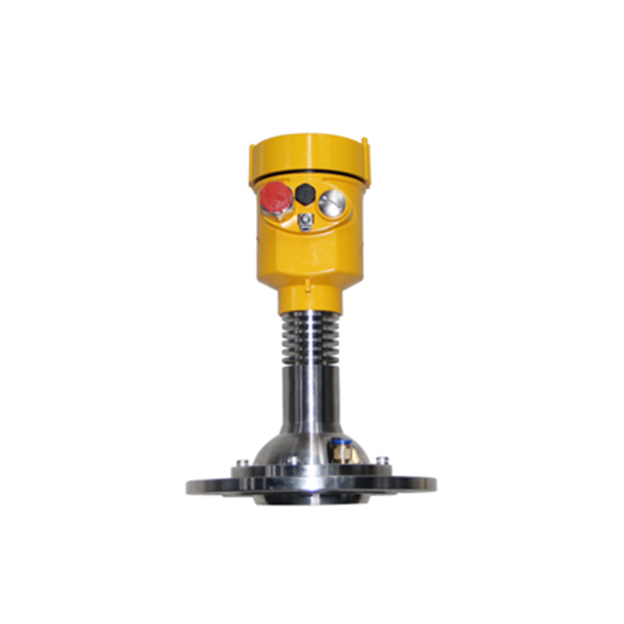
3. Analysis of Interference from Complex Environmental Factors
3.1 Gas Density Variations, Dust and Vapor
Ultrasonic Water Level Meter: When sound waves pass through high concentrations of dust, such as those found in cement silos or mining channels, or through high concentrations of water vapor, such as in power-plant cooling towers or asphalt mixing tanks, a large amount of acoustic energy can be scattered and absorbed by suspended particles. This causes severe signal attenuation and may even result in complete echo loss. In addition, if gas stratification or uneven gas density exists inside the vessel, acoustic refraction may occur due to changes in sound velocity, resulting in significant systematic measurement errors.
Radar Water Level Meter: Microwaves have strong propagation capabilities and are not physically affected by dust, water vapor, or suspended mist. The propagation characteristics of 80 GHz millimeter-wave radar allow liquid-surface reflections to be reliably returned even under extremely dusty or vapor-saturated operating conditions.
3.2 Liquid Surface Waves and Turbulence
Ultrasonic Water Level Meter: When mechanical sound waves encounter a severely fluctuating liquid surface or a liquid surface covered with large amounts of foam, diffuse reflection can occur. As a result, most of the reflected acoustic energy cannot return to the probe along the original propagation path, potentially causing blind-zone alarms or loss of measurement.
Radar Water Level Meter: High-frequency radar transmitters integrate advanced dynamic tracking algorithms such as echo suppression and false-echo filtering. Even when the liquid surface is rolling, turbulent, or covered with light foam, METRAVON radar water level meters can still identify and track the true liquid-surface echo from background noise.
3.3 Internal Tank Structures and Installation Beam Angle
The beam angle of an ultrasonic transmitter is typically between 6° and 12°, meaning that the transmitted energy is relatively dispersed. When reinforcement ribs, pipes, ladders, pumps, or other internal structures are present inside a tank or measuring well, sound waves can easily reflect from these obstacles and generate false level signals.
METRAVON 80 GHz radar water level meters can reduce the transmission beam angle to approximately 3°. The highly concentrated and extremely narrow beam can more easily avoid internal tank structures and narrow mounting nozzles, travel directly toward the liquid surface, and significantly reduce installation-space restrictions in field applications.
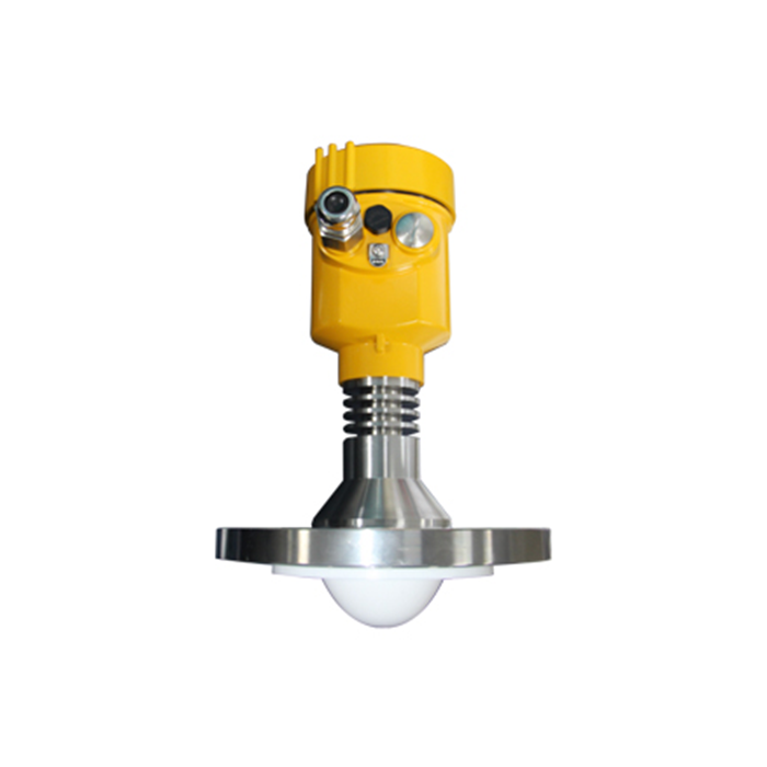
4. Selection Recommendations for Typical Industrial Applications
During engineering procurement and project design, the appropriate technology should be selected according to medium characteristics, available installation space, and project budget:
Level Measurement Selection Process
Step 1 – Evaluate the Process Environment: Determine whether the application involves severe dust, vapor, high temperature, high pressure, restricted installation space, or low-dielectric-constant media.
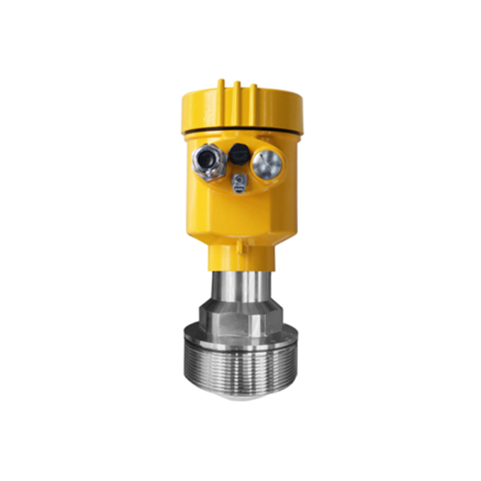
Step 2 – Harsh Industrial Conditions: For high dust, heavy vapor, high temperature, or high pressure, select an 80 GHz non-contact radar level transmitter, such as the METRAVON R-80 Series.
Step 3 – Restricted Space or Low Dielectric Constant: For small vessels, confined spaces, or low-dielectric-constant media, consider guided wave radar (GWR), such as the METRAVON GWR-70.
Step 4 – General Water and Open-Channel Applications: For ambient-temperature, atmospheric-pressure water applications without severe vapor or environmental interference, an ultrasonic water level meter, such as the METRAVON UT-20, can provide a cost-effective solution.
4.1 Applications Where Ultrasonic Water Level Meters Are Preferred
Municipal drainage and hydraulic open-channel flow measurement: In open Parshall flumes, triangular weirs, and river water-level monitoring applications without vapor interference, ultrasonic water level meters offer excellent cost performance. Their non-contact installation also eliminates corrosion-related maintenance requirements.
Ambient-temperature, atmospheric-pressure water tanks and clean-water reservoirs: For clean-water treatment basins, fire-water tanks, and agricultural irrigation channels without severe temperature fluctuations or strong wave action, ultrasonic technology can provide stable and reliable measurement while controlling overall project cost.
4.2 Applications Where Radar Water Level Meters Are Preferred
Mining and cement-industry dusty storage vessels: High-dust environments can cause ultrasonic measurement to fail completely. An 80 GHz radar level transmitter is a standard choice for continuous measurement in high-dust applications.
Asphalt mixing tanks, hydrocarbon storage tanks, and chemical storage pools: For volatile organic compounds (VOCs), high concentrations of vapor, and high-temperature environments above 80 °C, radar water level meters are not affected by changes in vapor refractive properties in the same way as ultrasonic instruments.
Narrow deep wells and reactors with complex agitators: The narrow beam angle of 80 GHz radar allows the signal to pass through confined spaces and reach the liquid surface while avoiding false echoes generated by agitator blades.
Low-dielectric-constant liquids such as liquefied gas and light petroleum products: Select a METRAVON guided wave radar water level meter (GWR). By focusing electromagnetic wave energy along a metal probe, continuous millimeter-level measurement can be achieved in applications with dielectric constants as low as approximately 1.4.
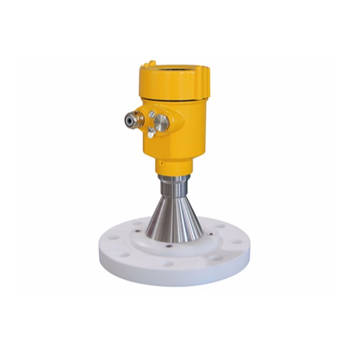
FAQ
Q1: Why can ultrasonic water level measurements differ between daytime and nighttime when the instrument is installed outdoors?
A: The direct cause is ineffective compensation for air-temperature gradients. Ultrasonic measurement depends on the speed of sound, and the speed of sound changes with temperature. For every 1 °C increase in temperature, the speed of sound increases by approximately 0.6 m/s. Although the sensor has a built-in temperature compensation element, compensation may become inaccurate when direct solar radiation heats the probe housing so that the internal sensor temperature is significantly higher than the actual air temperature along the acoustic propagation path. This can result in measurement deviation.
Procurement Recommendation: Outdoor ultrasonic water level meters should be equipped with a solar radiation shield. For high-accuracy hydrological monitoring applications, a METRAVON 80 GHz radar water level meter, which is not affected by the air-temperature field in the same way, is recommended.
Q2: How does a low dielectric constant, or low εr, affect a radar water level meter, and how can the problem be addressed?
A: The dielectric constant determines the proportion of electromagnetic energy reflected from the medium surface. When the dielectric constant is very low, such as diesel with εr of approximately 2.1 or liquefied gas with εr of approximately 1.4, a large proportion of the non-contact microwave energy may penetrate the medium instead of being reflected. This weakens the reflected signal and may make it difficult for the receiver electronics to identify the correct echo.
Solutions and Selection Conditions:
Select a METRAVON 80 GHz radar water level meter with highly concentrated transmitted energy.
Select a METRAVON guided wave radar water level meter (GWR), which uses a coaxial probe or cable-type probe to guide electromagnetic waves and minimize energy loss.
Q3: Can radar water level meters completely replace ultrasonic water level meters?
A: From a technical-performance perspective, radar technology can provide complete functional replacement. Radar water level meters provide advantages in accuracy, temperature and pressure resistance, resistance to environmental interference such as dust, vapor, wind, and temperature variation, and beam-angle control.
Procurement Recommendation: Equipment selection should balance technical requirements against project budget. Ultrasonic water level meters retain a significant cost advantage in ordinary water applications operating at ambient temperature and atmospheric pressure without vapor interference. If the project budget is sufficient or the operating conditions are demanding, upgrading the complete measurement system to radar water level meters should be considered.
Q4: Which type of water level meter provides more stable measurement in wastewater treatment tanks with large amounts of foam?
A: Foam can absorb both acoustic and microwave energy. However, guided wave radar (GWR) generally provides the greatest stability in this type of application because the guided wave probe can pass directly through the surface foam layer and measure the true liquid interface below using high-frequency electromagnetic signals. If non-contact measurement is mandatory, a high-frequency 80 GHz radar with multi-echo tracking algorithms should be selected. Ultrasonic water level meters are more likely to lose the signal because of diffuse reflection under these conditions.
Q5: What practical engineering impact does the blind zone have on level measurement?
A: The blind zone is the minimum distance directly below the sensor probe within which effective measurement cannot be performed. Due to transducer ring-down time, ultrasonic water level meters typically have a relatively large blind zone of approximately 0.25 m–0.8 m. If the liquid level rises into this zone, the sensor may output an incorrect full-scale signal, creating a potential tank-overflow risk. Radar water level meters generally have a much smaller blind zone, typically approximately 0.05 m–0.1 m, which can significantly improve usable storage-tank capacity.
Q6: How should ultrasonic and radar technologies be selected for open-channel flow measurement applications such as Parshall flumes?
A: Select an ultrasonic water level meter under the following conditions: municipal stormwater or wastewater open channels with no significant water vapor, no strong wind, and a limited project budget.
Select a radar water level meter under the following conditions: industrial wastewater discharge involving temperature differences and water vapor, high-velocity turbulent river channels, or outdoor reservoirs strongly affected by wind.
Procurement Recommendation: For key discharge monitoring projects operated by water authorities or industrial parks, a METRAVON radar open-channel flow measurement system is recommended to improve continuity of uploaded monitoring data and support regulatory compliance.
Q7: How should guided wave radar (GWR) and non-contact high-frequency radar be selected?
A: Guided Wave Radar: Suitable for highly viscous or adhesive media, extremely low-dielectric-constant liquids, narrow tanks with severe agitation, or solid-liquid interface measurement such as sludge-level measurement in settling tanks.
Non-Contact Radar: Suitable for highly corrosive liquids where probe corrosion should be avoided, viscous or crystallizing media, and hygienic food or pharmaceutical storage tanks where direct probe contact with the medium is not permitted.
Conclusion
There is no absolute superiority between radar water level meters and ultrasonic water level meters. The key consideration is matching the measurement principle to the actual operating conditions. Due to their high cost-effectiveness, ultrasonic water level meters remain a practical solution for ordinary open-channel water applications and conventional water tanks operating at ambient temperature and atmospheric pressure. Radar water level meters, particularly high-frequency 80 GHz microwave radar and guided wave radar technology, have become critical measurement instruments for complex industrial processes, hazardous storage vessels, and high-accuracy hydrological monitoring because of their strong physical resistance to interference from temperature, humidity, pressure, vapor, and dust.
As a provider of industrial process measurement and hydraulic monitoring solutions, METRAVON offers a complete product range covering 80 GHz high-frequency radar, guided wave radar, and industrial ultrasonic level transmitters. METRAVON also provides customized equipment selection and signal integration support for complex operating conditions. To optimize your level measurement solution or obtain detailed technical specifications and project pricing, please contact the METRAVON technical engineering team.
Related resources
Radar level meters · Level measurement
Author: Arvin · Source: METRAVON Instruments
