


 Chinese
 Spanish
 Russian
 Portuguese
 French
 German
 Indonesian
 Thai
Thai Vietnamese
 Arabic
 Italian
 Turkish
 Polish
 Japanese

1. Core Technical Principles and Types of Mining Radar Level Transmitters
In mining engineering, coal preparation plants, power-plant coal bunkers, and metallurgical material storage facilities, continuous material-level monitoring is critical for automated feeding and prevention of bunker overfilling and material overflow. Mining level measurement must operate under harsh conditions involving high dust concentrations, high humidity, material angle of repose, and strong mechanical impact. METRAVON industrial radar level transmitters mainly use the following two physical measurement mechanisms:
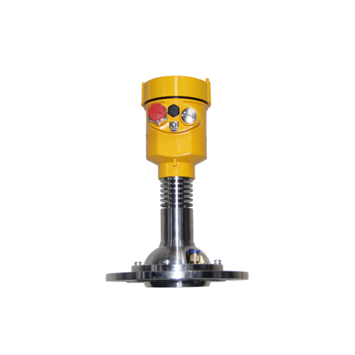
1.1 Time-Domain Reflectometry Guided Wave Radar (TDR / GWR)
Guided wave radar level transmitters operate according to the principle of Time Domain Reflectometry (TDR). High-frequency electromagnetic pulses travel along a guided steel cable or probe rod. When an electromagnetic pulse reaches the surface of the measured material, such as coal powder or mineral particles, part of the pulse energy is reflected because of the sudden change in the dielectric constant (Dielectric Constant, εr) of the medium. The reflected energy forms an echo and travels back along the guided element to the receiver.
The distance D between the transmitter and the material surface is proportional to the electromagnetic wave propagation time Δt and is calculated using the following formula:
D = (c × Δt) / 2
where c is the speed of light, approximately 3 × 10⁸ m/s. Because guided wave radar uses a conductor to guide electromagnetic energy, signal attenuation is very low, making it particularly suitable for mining storage vessels containing materials with relatively low dielectric constants or for applications with extremely limited measurement space.
Guided Wave Radar Measurement Process (TDR)
Step 1 – Pulse Generation: The transmitter generates a high-frequency electromagnetic pulse.
Step 2 – Guided Propagation: The pulse travels along the steel cable or probe rod toward the material surface.
Step 3 – Surface Reflection: When the pulse reaches the material surface, the change in dielectric constant εr causes part of the electromagnetic energy to be reflected.
Step 4 – Echo Return: The reflected pulse travels back along the same guided element to the receiving electronics.
Step 5 – Distance Calculation: The instrument measures the propagation time difference Δt and calculates the material distance using
D = (c × Δt) / 2.
1.2 Frequency-Modulated Continuous-Wave Radar (FMCW)
Frequency-Modulated Continuous-Wave (FMCW) radar level transmitters, such as METRAVON 80 GHz high-frequency radar, use non-contact measurement technology. The radar antenna transmits a microwave signal whose frequency increases linearly over time through linear frequency modulation.
After the microwave signal reaches the material surface, it is reflected and received by the receiving antenna. Because the transmitted signal frequency continuously changes, there is a frequency difference Δf between the received echo frequency and the currently transmitted frequency. This frequency difference is proportional to the measurement distance D:
D = (c × Δf) / (2 × K)
where K is the frequency sweep rate. Combined with the extremely high 80 GHz operating frequency, FMCW technology provides a very high signal-to-noise ratio and strong measurement capability, making it a preferred non-contact measurement technology for high-dust mining and coal-bunker applications.
FMCW Radar Measurement Process
Step 1 – Frequency Sweep: The radar oscillator generates an 80 GHz microwave signal whose frequency increases linearly over time.
Step 2 – Transmission: The antenna transmits the frequency-modulated microwave signal toward the bulk material surface.
Step 3 – Reflection: The microwave signal is reflected from the material surface, including inclined surfaces formed by the material angle of repose.
Step 4 – Echo Reception: The antenna receives the reflected microwave signal.
Step 5 – Distance Calculation: The electronics calculate the frequency difference Δf between the transmitted and received signals and determine distance using D = (c × Δf) / (2 × K).
2. Key Purchasing Criteria and Selection Parameters for Mining Radar Level Transmitters
For extreme operating conditions in underground and surface mining operations, procurement and engineering personnel should focus on the following five key technical parameters:
| Evaluation Dimension / Selection Parameter | Conventional Industrial Radar Level Transmitter | METRAVON Explosion-Proof Mining Radar Level Transmitter | Engineering Significance |
|---|---|---|---|
| Explosion-Proof Certification Level | Ex d IIC T6 Gb / Ex tD | Ex d I Mb (mining intrinsic-safety / flameproof configuration) | Meets compliance requirements for methane and coal-dust explosive atmospheres in underground coal mines |
| Microwave Operating Frequency | 26 GHz / 6 GHz | 80 GHz FMCW / 500 MHz TDR | 80 GHz provides an extremely narrow beam angle of approximately 3°, helping avoid interference from shaft walls and supporting structures |
| Measurement Range and Penetration Capability | 10 m–30 m | 0 m–120 m | Meets measurement requirements for deep raw-coal bunkers and large, tall gangue silos |
| Ingress Protection Rating (IP Code) | IP65 / IP67 | IP68 / IP69K | Provides protection against high-pressure water cleaning and humid underground condensation |
| Antenna Dust Protection and Self-Cleaning | No dedicated dust-protection structure / standard lens | PTFE lens antenna + air-purge connection | Helps prevent signal distortion caused by adhesion of sticky dust to the antenna surface |
3. Radar Level Transmitter Selection Strategies for Complex Mining Conditions
Mining Radar Level Transmitter Selection Process
Step 1 – Identify the Storage or Process Environment: Determine whether the application is a high-dust underground coal bunker, raw-coal silo, confined feed hopper, wastewater tank, or slurry tank.
Step 2 – High Dust and Non-Contact Measurement: For coal bunkers, gangue silos, and applications involving severe dust and material angle of repose, select an 80 GHz FMCW radar level transmitter, such as the METRAVON FMCW-80M.
Step 3 – Restricted Space or Low Dielectric Constant: For confined spaces or media with low dielectric constants, select a high-tensile guided wave radar, such as the METRAVON GWR-MINE.
Step 4 – Corrosive Wastewater or Slurry Applications: For narrow wastewater or slurry tanks requiring guided measurement and corrosion resistance, consider a corrosion-resistant guided wave radar level transmitter, such as the METRAVON GWR-70.
3.1 80 GHz FMCW Non-Contact Radar Level Transmitter: Main Coal Bunkers and Gangue Silos
Operating Conditions: Large material drop height, extremely high dust concentration, and inclined material surfaces caused by the angle of repose.
Selection Requirements: An 80 GHz FMCW radar with a transmission beam angle of ≤3° should be selected. The narrow beam helps penetrate the dust layer and focus the signal toward the center of the material pile, reducing false echoes from rough silo walls and internal structural surfaces. A pneumatic air-purge connection should also be selected so compressed air can periodically clean the antenna surface.
3.2 Guided Wave Radar Level Transmitter (GWR): Coal Blending Bunkers and Narrow Feed Hoppers in Coal Preparation Plants
Operating Conditions: Limited installation space, internal reinforcing beams and feeding devices, and large variations in material dielectric constant.
Selection Requirements: Select guided wave radar equipped with a heavy-duty steel cable with high tensile strength of no less than 20 kN. The guided steel cable confines electromagnetic energy around the cable and reduces interference from internal steel structures. Depending on the application design, the lower section of the cable may require a weight or suitable restraint arrangement to maintain cable position and reduce the risk of mechanical damage caused by collapsing material.
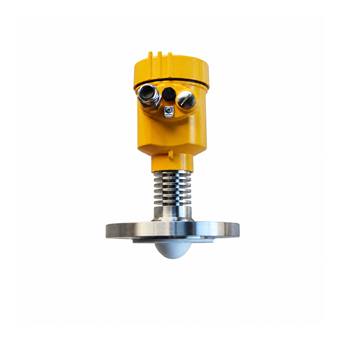
4. Engineering Installation and Explosion-Proof Requirements for Guided Wave Radar Level Transmitters
In mining and coal-washing engineering projects, standardized installation is critical for ensuring long-term stable instrument operation. The following are standard construction and installation procedures for guided wave radar level transmitters:
4.1 Installation Position and Obstacle-Avoidance Principles
Avoid the Material Inlet: The installation position must avoid areas subject to direct material impact to prevent large pieces of ore or other material from striking the steel cable or antenna. In polypropylene/polyethylene granulation and wastewater treatment tank applications, the instrument may be installed near the center. For outdoor rainwater drainage tanks, installation may be approximately 400 mm from the tank wall, with nearby obstacles removed.
Insulation Box and Wall-Contact Prevention: Install a 2-inch, 150lb flange at the threaded connection of the transmitter. If an insulation box is used, make a circular opening with a diameter of D = 50 mm at the bottom. First guide the steel cable through the center of the opening and then secure the flange inside the insulation box. Ensure that the steel cable does not touch the metal wall of the insulation box to avoid parasitic capacitance interference.
4.2 Electrical Explosion-Proof and Insulation Testing Requirements
Electrical Installation Process
Step 1 – Protective Enclosure: Route the instrument cable from the protective or insulation enclosure.
Step 2 – Cable Conduit: Use DN20 galvanized steel conduit with secure threaded connections.
Step 3 – Intrinsically Safe Cable: Route the flame-retardant intrinsically safe signal cable through the conduit toward the instrument.
Step 4 – Cable Gland and Drip Loop: Tighten the cable gland and create a downward drip loop before the cable enters the housing to prevent condensation from traveling into the instrument.
Step 5 – Explosion-Proof Junction and Grounding: Complete the connection in accordance with the explosion-proof wiring requirements and connect the cable shield to the designated grounding point using single-point grounding.
Power Isolation: Before disassembling or installing the instrument, the power supply must be disconnected in the control cabinet, and the positive and negative signal wires must be disconnected.
Cable Installation: Use a 1 mm × 2 mm × 1.5 mm flame-retardant intrinsically safe cable. The conduit should be DN20 galvanized steel pipe with securely tightened threaded connections.
Insulation Test: After cable installation is completed, perform an insulation test using a megohmmeter. Set the test voltage to 500 V DC and test continuously for 60 seconds. The insulation resistance must be ≥20 MΩ.
Waterproof and Moisture Protection (Drip Loop): The instrument cable gland must be securely tightened. At the signal cable entry, bend the cable downward and form a circular drip loop with a diameter of approximately D = 100 mm to prevent condensate and water vapor from traveling along the cable into the instrument housing.
Grounding Requirements: The shielding layer of the shielded cable must be grounded at a single point to the dedicated internal grounding terminal of the level transmitter housing. Power may only be restored after confirming that there is no unintended ground fault or short circuit.
4.3 High-Level Limit and Blind Zone Settings
When using a radar level transmitter, the maximum material level must never enter the measurement blind zone.
High-Level Limit Setting: When configuring the high-level alarm, sufficient clearance must be reserved for the instrument's inherent upper blind zone. A typical reference range is approximately 0.1 m–0.3 m for non-contact radar and approximately 0.2 m–0.5 m for guided wave radar, depending on the specific instrument design.
Overfill Prevention Logic: If the maximum material level reaches the blind zone, strong reflections near the antenna may cause the output to lock at the maximum level or trigger a "Loss of Echo" alarm, which may result in incorrect control-system actions.
FAQ
Q1: Why are METRAVON explosion-proof radar level transmitters widely used in the mining and metallurgical industries?
A: The main reasons are their reliable explosion-protection design and strong resistance to environmental interference. METRAVON explosion-proof radar level transmitters are designed for demanding hazardous-area applications, with intrinsically safe and flameproof protection configurations available according to model requirements. At the same time, 80 GHz high-frequency microwave measurement provides strong resistance to interference from high dust concentrations, water vapor, environmental pressure changes, and significant temperature variations, offering improved measurement stability compared with conventional ultrasonic and lower-frequency radar technologies in many mining applications.
Q2: What advantages does Frequency-Modulated Continuous-Wave (FMCW) radar provide over pulse radar in coal bunker measurement?
A: FMCW radar continuously transmits signals throughout the frequency sweep cycle and can provide a high signal-to-noise ratio. Coal and similar bulk materials often have loose, inclined surfaces and can strongly attenuate microwave reflections. FMCW signal processing can help identify weak but valid material echoes and reduce the probability of "Loss of Echo" under difficult measurement conditions.
Q3: Will high concentrations of water vapor and condensation underground affect radar level measurement accuracy?
A: Water vapor itself generally has limited effect on microwave propagation velocity. However, if vapor condenses into water droplets on the radar antenna surface, microwave energy can be attenuated. METRAVON radar level transmitters can use raised PTFE lens antennas with hydrophobic characteristics. Combined with an explosion-proof pneumatic air-purge assembly where applicable, this design helps reduce the effects of condensation on measurement.
Q4: How should reflected-wave deflection caused by the material angle of repose be handled in mining bulk-solid measurement?
A: An inclined material surface can reflect part of the microwave energy toward the silo wall instead of back toward the antenna. Recommended solutions include:
Use a METRAVON 80 GHz radar transmitter with an approximately 3° narrow beam angle to reduce scattering;
Use an adjustable aiming flange during installation to adjust the radar antenna angle so that the beam is directed more perpendicularly toward the inclined material surface;
Enable the instrument's internal material-surface tracking or false-echo processing functions where supported.
Q5: How can the guided wave radar steel cable be protected from excessive tension or breakage during material discharge?
A: The following three points should be considered during selection and installation:
Calculate the maximum pulling force exerted by the material on the cable and select a heavy-duty cable with an appropriate breaking strength, such as greater than 20 kN where required by the application;
Avoid installing the guided wave radar directly below the material inlet or at the center of the bottom discharge outlet;
Use a suitable mounting method according to the mechanical loading conditions, such as top suspension with free lower-end hanging or an engineered flexible lower restraint where appropriate.
Q6: Which materials can intelligent radar level transmitters measure?
A: Intelligent radar level transmitters are widely used for coal bunkers in coal plants, ash silos in power plants, acid and alkali storage tanks in petrochemical facilities, slurry tanks, metallurgical ore bins, and food-grain silos. Both conductive media and many low-dielectric-constant non-conductive materials, such as light petroleum products and dry powders, can be measured when the appropriate radar technology and configuration are selected.
Q7: In what order should a "Loss of Echo" alarm from a radar level transmitter be investigated?
A: First, check whether the maximum material level has risen into the antenna blind zone;
Check whether thick, sticky dust or wet coal slurry has accumulated on the antenna surface;
Check whether the air-purge supply pressure is normal;
Check the instrument power-supply voltage and the insulation resistance of the flame-retardant cable, including whether the insulation resistance remains above 20 MΩ.
Conclusion
Selecting a mining radar level transmitter requires comprehensive consideration of explosion-protection rating, material dielectric constant, dust concentration, and the geometric dimensions of the measurement space. For high-dust, long-range underground coal bunkers and tall gangue silos, 80 GHz FMCW radar level transmitters provide a strong combination of accuracy and stability. For narrow spaces, low-dielectric-constant materials, or slurry tanks, guided wave radar (GWR) offers important technical advantages.
As a professional manufacturer serving industrial process control and mining measurement applications, METRAVON provides a complete range of explosion-proof radar level transmitters together with field selection guidance for customers in the global mining, metallurgical, and power industries. To obtain mining explosion-proof certification documents, technical datasheets, or project procurement quotations, please contact the METRAVON engineering team.
Related resources
Radar level meters · Level measurement
Author: Arvin · Source: METRAVON Instruments
