


 Chinese
 Spanish
 Russian
 Portuguese
 French
 German
 Indonesian
 Thai
Thai Vietnamese
 Arabic
 Italian
 Turkish
 Polish
 Japanese

1. The Core of Radar Level Transmitter Commissioning Is Not Simply “Making the Display Correct”
After a radar level transmitter has been installed, field commissioning is usually required before the instrument is placed into normal operation.
The purpose of commissioning is not merely to make the number shown on the local display match the current liquid level. The real objective is to establish a correct and complete measurement chain:
Complete Radar Level Measurement Chain
Step 1 – Geometric Parameters: Define the correct tank dimensions and instrument reference point.
Step 2 – Radar Distance Measurement: The radar measures the distance from the reference plane to the product surface.
Step 3 – Level Conversion: The instrument converts the measured distance into the corresponding level value.
Step 4 – Analog or Digital Output: The measured level is converted into a 4–20 mA or digital communication signal.
Step 5 – PLC/DCS Display: The control system interprets the signal and displays the final engineering value.
If only one offset parameter is changed so that the current liquid level “looks correct,” significant measurement errors may still occur when the tank level changes.
Therefore, radar level transmitter commissioning should normally include:
Installation inspection;
Basic parameter configuration;
Echo inspection;
Output configuration;
Interlock and PLC verification;
Dynamic level-change testing.
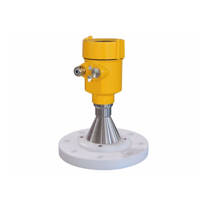
2. Check the Installation Before Starting Commissioning
Commissioning software cannot correct mechanical installation errors.
Before configuring parameters, check the following items:
Whether the antenna is generally directed toward the measured liquid surface;
Whether the mounting nozzle is excessively long;
Whether the antenna is obstructed by the mounting nozzle;
Whether the radar is installed directly above the filling inlet;
Whether obvious obstacles exist within the radar beam path;
Whether the mounting flange is level;
Whether any protective cap or packaging material remains on the antenna;
Whether the cable entry is correctly sealed;
Whether grounding complies with site requirements.
If the tank contains agitators, heating coils, support structures, or other internal components, their approximate distances from the radar should be recorded in advance. This information can later be used when analyzing the echo curve.
3. First Set the Empty-Tank Distance and Full-Tank Distance
The basic variable measured by most radar level transmitters is:
The distance from the antenna reference plane to the surface of the measured medium.
The instrument then converts this distance into a level value according to the known tank geometry.
Using a common definition:
E = Empty-tank reference distance;
D = Current distance from the radar reference plane to the liquid surface;
L = Current liquid level.
The relationship is:
L = E − D
This is the basic level-conversion logic commonly used for time-of-flight radar measurement.
For example:
The distance from the tank bottom to the radar reference point is 10 m.
The radar currently measures a distance of 4 m from the antenna to the liquid surface.
The liquid level is therefore approximately:
10 − 4 = 6 m
If the empty-tank distance is entered incorrectly by 500 mm, the displayed level across the measurement range may contain a corresponding offset.
4. Confirm Which Liquid Levels Correspond to 4 mA and 20 mA
The 4–20 mA measurement range must correspond exactly with the control-system configuration.
For example:
4 mA = 0 m;
20 mA = 10 m.
For a 10 m full-scale range:
12 mA should correspond to approximately 5 m.
If the field instrument is configured for 0–10 m but the PLC is configured for 0–8 m, the control-room display will still be incorrect even if the radar itself is measuring perfectly.
During commissioning, verify the following parameters at both the instrument and control-system sides:
Instrument LRV;
Instrument URV;
PLC analog input range;
Engineering units;
Whether 4 mA corresponds to the low level or high level.
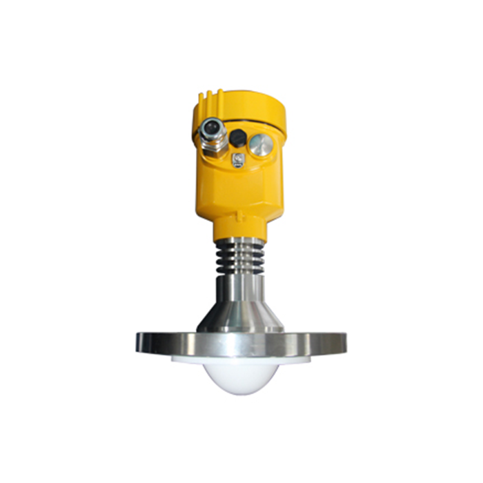
5. What Methods Can Be Used to Commission a Radar Level Transmitter?
Common commissioning methods mainly include the following:
5.1 Local Display and Adjustment Module
The buttons or magnetic keys on the instrument can be used to configure:
Empty-tank setting;
Full-tank setting;
Engineering units;
Damping;
Output settings;
Medium type.
This method is suitable for quick field commissioning.
5.2 HART Handheld Communicator
For radar level transmitters supporting 4–20 mA/HART communication, a compatible HART communicator can be used to read instrument parameters and diagnostic information.
5.3 PC Commissioning Software
Engineering software can usually display more detailed diagnostic information, including:
Echo Curve;
Threshold curve;
False echoes;
Currently detected target;
Signal strength;
Fault history.
For complex tanks, it is preferable to analyze the echo curve through commissioning software rather than relying only on the value displayed on the LCD.
5.4 Bluetooth or Mobile Device
Some newer radar level transmitters support Bluetooth configuration through mobile devices. Availability depends on the specific instrument model.
6. Why Is the Echo Curve Critical During Commissioning?
A radar level transmitter transmits electromagnetic waves toward the material or liquid surface and receives the reflected signals.
In a real storage tank, the instrument usually receives more than one echo.
Possible reflected signals include:
Mounting nozzle echo;
Tank-roof structure echo;
Tank-wall echo;
Ladder echo;
Heating-coil echo;
Agitator echo;
Actual liquid-surface echo.
One of the main purposes of commissioning software is to help engineers determine which target the radar is currently tracking.
Basic Echo Curve Diagnostic Process
Step 1 – Compare the Displayed Distance: Check the distance or level currently identified by the radar.
Step 2 – Compare with the Actual Level: Determine whether the displayed value corresponds to the known or estimated liquid surface.
Step 3 – Check Internal Structures: If the displayed distance is incorrect, identify whether a nozzle, ladder, coil, agitator, or other structure exists at approximately that distance.
Step 4 – Analyze the Echo Curve: Compare the strength and position of the true level echo with nearby false echoes.
Step 5 – Optimize the Configuration: Correct installation, adjust signal-processing parameters, or apply false-echo suppression only when necessary.
If the instrument currently displays 3.2 m but the actual liquid surface is clearly not at the corresponding position, the engineer should check what tank structure exists around the 3.2 m distance.
7. When Should False-Echo Mapping Be Performed?
False-echo mapping or false-echo suppression is generally used to suppress strong reflections caused by fixed internal obstacles.
It is recommended to perform this function only after:
The actual liquid level is known;
The internal tank structure is understood;
The instrument installation has been finalized.
If the actual liquid level is unknown, or if the true liquid-surface echo is accidentally included within the false-echo mapping range, subsequent measurement may fail.
Therefore, false-echo suppression is a commissioning tool rather than a mandatory procedure that must be performed on every project.
8. How Should the Damping Time Be Set?
When the liquid level fluctuates significantly, some users directly increase the damping value.
This can make the displayed trend more stable, but it also introduces response delay.
The appropriate damping value should be selected according to the actual process dynamics.
For example:
Large storage tanks with very slow level changes can use a smoother output with longer damping;
Small batching tanks with rapid filling and emptying should not use excessive damping;
Applications requiring rapid high-level or low-level alarm response must pay particular attention to response time.
Therefore, a larger damping value is not always better.
9. How to Perform a 4–20 mA Loop Test
Many radar level transmitters provide an output simulation function.
For example, the instrument may temporarily simulate:
4 mA;
12 mA;
20 mA.
The corresponding PLC display can then be checked:
4 mA → 0 %;
12 mA → 50 %;
20 mA → 100 %.
Some industrial instruments also allow the user to simulate distance or level process variables to verify the complete signal chain. Similar current-output and process-variable simulation functions are widely used in industrial transmitters to verify the signal path from the field instrument to the control system.
4–20 mA Loop Verification Process
Step 1 – Simulate 4 mA: Confirm that the PLC or DCS displays the configured low-range value, typically 0 %.
Step 2 – Simulate 12 mA: Confirm that the control system displays approximately 50 % of the configured range.
Step 3 – Simulate 20 mA: Confirm that the PLC or DCS displays the configured upper-range value, typically 100 %.
Step 4 – Check Scaling: If the percentages are correct but the engineering value is wrong, verify the PLC LRV, URV, and engineering-unit configuration.
Step 5 – Exit Simulation Mode: After testing, restore the instrument to normal measurement mode.
After completing the test, the instrument must be taken out of simulation mode.
10. Final Acceptance After Radar Level Transmitter Commissioning
After commissioning is completed, it is recommended to verify at least three measurement points:
Low level;
Mid level;
High level.
If actual filling and emptying cannot be performed under site conditions, the radar reading can be checked against a manually measured level, gauge reading, historically reliable instrument, or another trustworthy reference.
The final commissioning record should include:
Empty-tank distance;
Measurement range;
Values corresponding to 4 mA and 20 mA;
Damping setting;
Fault-output configuration;
False-echo suppression status;
Instrument address;
Communication parameters.
Maintaining these records allows the original configuration to be restored quickly if problems occur later.
FAQ
Q1: Must the tank be empty before commissioning a radar level transmitter?
A: Usually not. However, the current liquid level or the tank geometry must be accurately known. The actual liquid-surface position is especially important when performing false-echo mapping.
Q2: Does a radar level transmitter need to be calibrated by filling the tank with water?
A: Non-contact radar primarily measures distance. In many applications, it does not require calibration with a standard liquid in the same way as some analytical instruments. However, the installation reference point and measurement range must be configured correctly.
Q3: How do you adjust the 4 mA and 20 mA values of a radar level transmitter?
A: Configure the LRV and URV in the measurement-range or Current Output settings, and make sure these values correspond exactly to the PLC analog input scaling.
Q4: Why should the echo curve be checked during commissioning?
A: The LCD only shows the final measurement result. The echo curve helps determine whether the instrument is actually tracking the liquid surface or an internal tank obstacle.
Q5: If the displayed liquid level keeps fluctuating, can the damping value simply be increased?
A: Increasing damping can be used as an optimization method, but the engineer should first determine whether the fluctuations are caused by false echoes, agitation, foam, or installation problems.
Q6: Can HART be used to commission a radar level transmitter?
A: Yes. If the instrument supports 4–20 mA/HART communication, compatible HART tools can be used to read and configure the relevant parameters.
Q7: What should be checked if the PLC reading does not match the radar's local display?
A: First verify the PLC measurement range, engineering units, 4–20 mA scaling relationship, and wiring. Then measure the actual loop current to determine whether the problem is on the instrument side or the control-system side.
Q8: What field information does METRAVON require for radar commissioning support?
A: It is recommended to provide the radar model, tank height, measured medium, installation photos, current actual level, instrument display value, output current, and screenshots of the echo curve.
Conclusion
Radar level transmitter commissioning should be completed in the following sequence:
Recommended Radar Commissioning Sequence
Step 1 – Installation Confirmation
Step 2 – Geometric Parameter Configuration
Step 3 – Measurement Range Setting
Step 4 – Echo Analysis
Step 5 – Output Testing
Step 6 – PLC/DCS Integration Test
Step 7 – Dynamic Measurement Verification
High-quality commissioning is not simply about adjusting the current number until it appears correct. The objective is to ensure that the entire measurement chain operates correctly across the full measurement range.
For complex storage tanks, METRAVON recommends retaining the initial configuration parameters and echo-curve records during project commissioning so that they can be used for future maintenance, troubleshooting, and fault analysis.
Related resources
Radar level meters · Level measurement
Author: Arvin · Source: METRAVON Instruments
