


 Chinese
 Spanish
 Russian
 Portuguese
 French
 German
 Indonesian
 Thai
 Vietnamese
 Arabic
 Italian
 Turkish
 Polish
 Japanese


An RF admittance level switch detects whether material has reached a sensing location. It does not provide a continuous inventory value simply because the probe extends into a vessel. For a hopper alarm or a tank high-level signal, the useful purchase question is whether the switch can distinguish genuine coverage from the residue left after material falls away.
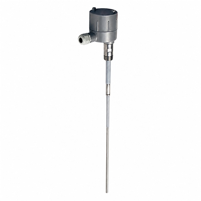
What the RF admittance level switch measures
The sensing arrangement responds to a change in electrical admittance as material reaches or leaves the probe. Admittance describes the response of a circuit to an alternating electrical signal. The medium, probe insulation and surrounding reference structure all contribute to that response. A change of material or installation can therefore matter even when the probe length stays the same.
METRAVON MV-SP601 is the relevant point-level model for this assessment. Its product information identifies rod and cable arrangements and circuitry intended to reduce the influence of adhering material. Supply, output, probe construction and process ratings need confirmation for the ordered configuration. A general description of RF admittance technology is not evidence that this switch has a continuous 4-20 mA level output.
Describe the residue, not just the word "sticky"
Coating rejection is intended to help separate a material-level change from an unwanted coating response. It is not a guarantee that a probe buried in hardened deposits will report an empty hopper. A thin residual film, a conductive bridge to nearby metal and a large lump around the probe are different installation problems.
Give the supplier observations from both filling and emptying. Does the residue drain, remain wet, dry into a crust or accumulate over repeated cycles? Does a different batch behave differently? Photos of the proposed sensing location and a description of cleaning methods are more useful than a statement that the product is generally suitable for powders or liquids.
| State | What the test should establish | What could mislead |
|---|---|---|
| Clear | The probe is genuinely uncovered and the expected state reaches the controller. | An empty-vessel label may hide a deposit at the sensing location. |
| Covered | Representative material reaches the intended active part of the probe and switches the output. | A convenient test object may not reproduce the actual material response. |
| Residue | After material recedes, normal remaining deposits do not prevent the required return state. | A test performed only with a newly cleaned probe omits this condition. |
| Power loss | The receiving system responds to loss of supply according to the approved control design. | The local indicator alone cannot prove how a PLC interprets the signal. |
Choose a location that represents the process
A probe beside a persistent wall deposit can detect that deposit correctly while giving the wrong impression of bulk level. A probe in a filling stream may change state whenever material passes it, even if the average hopper level is lower. Move the proposed sensing point on the drawing until it represents the condition the alarm is intended to detect.
For a rod arrangement, check the mounting connection, active sensing region, projection into the vessel and likely impact from material. For a cable arrangement, add swing space, loading and the possibility of contact with surrounding structures. Confirm any restraint with the supplier; do not improvise a cable anchor or treat the sensing probe as a structural support.
The return path also belongs in the application review. Describe non-metallic vessels, internal linings and unusual mounting adapters. Do not assume that a change from a metal vessel to a plastic vessel leaves the electrical sensing arrangement unchanged. Obtain the specified reference and grounding arrangement for that construction.
Write down the required action for each state
Separate the process condition from the electrical state. "High alarm" does not say which contact closes, which PLC input value represents the alarm, or what happens if power fails. Identify covered, uncovered and power-loss behaviour in the control narrative and confirm the selected output can implement it.
Also distinguish alarm indication from a safety function. A high-level switch used by ordinary control logic is not automatically an independently approved overfill protection system. Where the consequence of a missed alarm is serious, the project must establish the required architecture, approvals and verification separately.
At commissioning, record the probe arrangement, settings, observed material state, local output and receiving input. Demonstrate both directions of the transition. If a delay is configured, check that it rejects the intended brief disturbance without hiding a sustained high or low condition. Use the project's agreed timing requirement, not an arbitrary delay copied from another installation.
Send the material, normal residue behaviour, desired sensing point, vessel construction and installation sketch to METRAVON. Add operating and cleaning conditions, required output, power-loss action and any hazardous-area requirements. Ask for the probe arrangement and electrical version to be identified in the offer.
Questions about selection and testing
Q1. Can one switch report both the top and bottom of a vessel?
Do not assume that a high/low operating-mode selection provides two independent sensing elevations. Establish how many points the process requires and how the selected hardware detects them. A requirement for two separate alarm heights may need separate sensing points or a different measurement arrangement.
Q2. Is a longer probe a larger continuous measuring range?
Not for a point-level duty. Length positions the sensing arrangement and changes its mechanical requirements. Confirm the active sensing geometry and installation drawing rather than treating every centimetre of probe as an independently measured level.
Q3. Should sensitivity be increased whenever a switch misses material?
First check material coverage, probe placement, connections and the relevant settings against the manual. Increasing sensitivity without checking the uncovered, coated state may exchange a missed detection for a persistent false alarm. Retest both conditions after an authorised adjustment.
Q4. Can the switch be accepted using only an electrical simulation?
A simulation can establish that downstream indication and control logic respond. It does not demonstrate material detection or recovery after coating. Keep electrical checks and representative process checks as separate entries in the acceptance record.
Summary
Approve an RF admittance switch only after it has a defined sensing point and a credible distinction between covered, uncovered and normally coated conditions. For MV-SP601, connect the probe choice to the actual material behaviour and verify the complete alarm path. Continuous level measurement remains a separate requirement.
