


 Chinese
 Spanish
 Russian
 Portuguese
 French
 German
 Indonesian
 Thai
 Vietnamese
 Arabic
 Italian
 Turkish
 Polish
 Japanese


A float meter can produce a convincing electrical signal while its float is obstructed. Float level meter installation therefore needs a mechanical check before output adjustments are used to match the tank. Verify that the selected float can move through the required interval in the actual liquid.
Check the complete travel envelope
Review the float, stem or linkage arrangement shown on the manufacturer's drawing. Confirm mounting orientation, stops and any transport restraint before operation. Do not reverse a float, move stops or bend a stem to change the switching or measuring direction without the exact model's procedure.
Show the vessel wall, nozzle bore, internal pipes and agitator envelope on the installation section. Clearance in an empty vessel does not prove clearance during filling if the float or supporting structure can move sideways. Avoid using the cable as a lifting or locating device unless its design explicitly permits that use.
Float level meter installation checks before calibration
| Check | Reason to resolve it first |
|---|---|
| Float identity | The intended liquid and density determine whether the selected float is appropriate. |
| Orientation | The assembly may depend on a specified direction and locating arrangement. |
| Clearance | Contact with a wall, stop or deposit can prevent representative movement. |
| Output | The receiver must interpret the actual continuous or switching function correctly. |
Follow the approved inspection and isolation procedure. A hand-moved mechanism in a workshop may demonstrate movement but not buoyancy in the operating liquid. Conversely, an electrical signal simulation can leave a mechanical obstruction completely untested.
When non-contact measurement is worth assessing
If recurring deposits or restricted travel make the float arrangement unsuitable, the METRAVON MV-RD12 can be assessed as a liquid radar alternative. Its 32 mm PTFE lens requires an appropriate view of the liquid; it does not use the old stem or float and is not a plug-in replacement for those components.
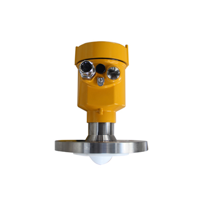
Compare the actual process connection, available headroom, surface conditions and output requirements. An advantage in avoiding float travel must not be converted into a promise that radar will ignore foam, condensation or nearby structures.
Keep the commissioning observations separate
Record mechanical condition, available local indication and receiving value at each approved test condition. If the float reaches an unintended stop, correct the installation through the authorised procedure rather than scaling the restricted movement to look like the full tank range.
Q1. Does a changing resistance prove the meter is ready for service?
A changing resistance demonstrates only the response observed at those terminals; it does not establish unrestricted float travel or buoyancy in the operating liquid. Check the float's orientation and movement using the approved method, then verify how the receiving instrument converts the specified output. Record any simulated input separately from an actual movement test, so a correct display does not conceal a restricted mechanism.
Q2. Can a water trial qualify a float for another liquid?
A water trial establishes the conditions actually tested, not suitability for another liquid. Compare the selected float's documented density limits, operating temperature and exposed materials with the intended service. Include viscosity and deposits when planning movement and return checks. If representative process testing is not practical, identify the remaining unverified conditions before accepting the installation.
Summary
Prove the physical motion before adjusting its reported value. Send the travel drawing, liquid information and recurring fault observations when assessing an MV-RD12 alternative.
