


 Chinese
 Spanish
 Russian
 Portuguese
 French
 German
 Indonesian
 Thai
Thai Vietnamese
 Arabic
 Italian
 Turkish
 Polish
 Japanese

In modern industrial process automation and warehouse management, continuous level measurement is directly related to production efficiency and asset safety. With the advantages of non-contact measurement, high accuracy, high reliability, and extremely low maintenance requirements, high-frequency radar level meters have become an important measurement solution for bulk solids, liquid process vessels, and complex operating conditions involving heavy dust and condensation.
This article provides an in-depth explanation of the working principle, performance characteristics, and technical requirements for flange installation and commissioning of high-frequency radar level meters, providing an objective technical reference for system integrators, engineering contractors (EPCs), and industrial customers.
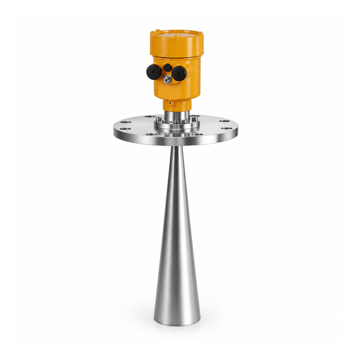
I. Working Principle of High-Frequency Radar Level Meters
High-frequency radar level meters use a high-frequency microstrip circuit design. The internal circuitry generates high-frequency microwave pulse signals at 26 GHz, or in some models 24GHz/25 GHz.
Signal transmission: Based on high-frequency waveguide design principles, microwave pulses are transmitted from the end of a highly corrosion-resistant antenna, such as a PTFE (polytetrafluoroethylene) antenna, toward the surface of the measured medium.
Energy reflection and reception: When the transmitted pulse reaches the surface of the measured medium, part of the microwave energy is reflected because of the change in dielectric constant at the interface. The reflected signal is received by the same antenna.
Time-domain calculation: The instrument contains an intelligent microprocessor that uses high-precision time-domain measurement technology (Time Domain Reflectometry / Time-of-Flight) to accurately calculate the time interval Δt between microwave pulse transmission and reception.
Distance and level calculation: Based on the electromagnetic wave propagation speed c, the instrument calculates the distance D from the antenna reference plane to the surface of the measured medium, and then converts this distance into the real-time level according to the vessel geometry:
D = c × Δt / 2
II. Core Features and Technical Advantages of High-Frequency Radar Level Meters
The maximum measurement distance of a high-frequency radar level meter can reach 30 meters. Compared with traditional 6GHz low-frequency radar, high-frequency radar such as 26 GHz provides significant technical advantages in physical characteristics and adaptability to demanding operating conditions:
| Technical Dimension | Advantages of High-Frequency Radar (26 GHz / 24GHz) | Limitations of Low-Frequency Radar (6GHz) |
|---|---|---|
| Wavelength and Beam Angle | Shorter wavelength, such as approximately 11 mm at 26 GHz, with a narrow beam angle and highly concentrated energy | Wider beam angle, greater energy dispersion, and higher susceptibility to interference from internal tank obstacles |
| Solids and Inclined Surfaces | The narrow beam provides excellent reflection performance from inclined bulk-solid surfaces | Reflected echoes from inclined bulk-material surfaces may be significantly attenuated |
| Antenna Size and Installation | Compact antenna size facilitates installation on small tanks or narrow mounting nozzles | Larger antenna size requires more installation space |
| Adaptability to Harsh Environments | Dust covers or anti-condensation protection surfaces can be added more easily, significantly reducing the effects of contamination and moisture accumulation | The antenna may be more susceptible to condensation and crystallized deposits |
| Isolated Measurement Capability | Strong directionality allows measurement through suitable non-metallic isolation windows under certain demanding operating conditions | More difficult to achieve accurate measurement through an isolation layer |
Core Technical Features Summary
High signal-to-noise ratio and interference resistance: Clear and reliable echoes can still be captured when the medium surface fluctuates significantly or when vapor and water mist are present.
Adaptability to low-dielectric-constant media: Suitable for measuring liquids with relatively low dielectric constants, such as light oils and solvents, as well as bulk solid materials.
Strong environmental adaptability: Measurement can be applied under vacuum, high dust concentrations, corrosive environments, and significant gas temperature or pressure variations, subject to the technical limits of the selected model.
No mechanical wear: The non-contact measurement design eliminates mechanical wear, does not contaminate the medium, and requires very little maintenance.
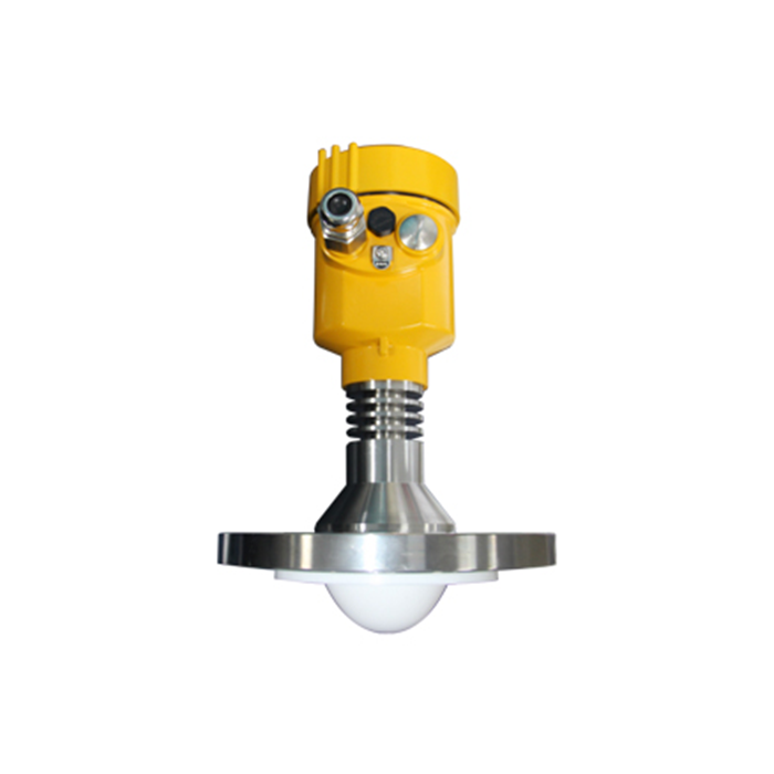
III. Technical Requirements for High-Frequency Radar Level Meter Flange Installation
As the core process connection between the radar level meter and the vessel, the flange installation orientation and angle directly determine the microwave beam path and echo quality.
1. Orientation Rules for Flange Reference Marks
Flanges are typically provided with an orientation reference mark. During on-site bolt tightening, the following alignment rules should be observed:
Conventional tank installation: The flange reference mark should be accurately oriented toward the tank wall or the geometric center of the storage tank so that the microwave beam avoids internal ladders, pipes, and other structures.
Installation in a stilling well: When a stilling well is used, the flange reference mark should be accurately oriented toward the side containing the stilling-well opening, such as a vent hole or equalization hole.
Installation in a bypass chamber: When a bypass chamber is used, the flange reference mark should point toward the side containing the upper and lower connection pipes to the main storage tank.
2. Physical Adjustment of Interference Echoes and Echo Storage
During initial commissioning, echo signal amplitude is a key indicator for evaluating whether the installation position is correct. A low signal amplitude usually indicates installation deviation, obstruction, or an unfavorable beam path.
Physical rotational adjustment: If excessive background noise or interference echoes are detected, slightly loosen the flange bolts and rotate the flange clockwise or counterclockwise by one bolt-hole position at a time. Observe the waveform on the commissioning interface until the interference echo amplitude is minimized.
False Echo Suppression: After completing the physical rotational adjustment, enable the echo-learning function through the instrument menu or commissioning software. Static interference generated by fixed metal structures inside the tank can then be stored in the suppression mask to improve long-term measurement accuracy.
IV. METRAVON System Integration and Engineering Compatibility
As a professional supplier of industrial automation measurement instruments and solutions, METRAVON designs its radar level meters and broader range of industrial instrumentation for integration into on-site automation systems.
Complete industrial automation instrument portfolio: The product range covers liquid level instruments, solids level instruments, flow instruments, temperature instruments, pressure instruments, display instruments, valves, pneumatic and electric actuators, intelligent instruments, and programmable logic controllers (PLCs), providing one-stop support for process control procurement.
Standard industrial communication interfaces: METRAVON high-frequency radar level meters natively support standard 4–20mA + HART and RS-485 (Modbus RTU), with optional expansion to PROFIBUS-PA and FOUNDATION Fieldbus.
Seamless DCS/SCADA integration: Complete DTM/EDD driver files are available for direct integration with mainstream DCS platforms from Honeywell, Yokogawa, Schneider, Siemens, and third-party industrial monitoring platforms, supporting remote status diagnostics and reliable data acquisition.
FAQ
Q1: Why Is 26 GHz High-Frequency Radar More Suitable Than 6GHz Low-Frequency Radar for Small Storage Tanks?
Small storage tanks typically have limited internal space and may contain agitators or reinforcing structures. A 26 GHz high-frequency radar has a narrow beam angle with concentrated energy and a compact antenna. Its narrow microwave transmission path helps avoid tank walls and internal obstacles, thereby reducing severe multiple-reflection interference.
Q2: How Can Radar Antenna Contamination and Signal Attenuation Be Reduced in Heavy Dust or High-Humidity Environments?
High-frequency radar antennas are compact and can easily be fitted with PTFE dust-protection covers or antenna protection surfaces. Under severe dust conditions, a flange with an instrument-air Air Purging interface can also be selected to periodically remove deposits from the antenna surface.
Q3: Why Can Rotating the Flange Reduce Interference Echoes?
The microwave signal emitted by a high-frequency radar has polarization characteristics. Rotating the flange changes the physical orientation of the microwave polarization plane, which can reduce the reflected energy from internal metal structures and lower the amplitude of interference echoes.
Conclusion
With its 26 GHz narrow beam, strong measurement capability, high signal-to-noise ratio, and excellent resistance to environmental interference, the high-frequency radar level meter has become an important solution for continuous level monitoring in industrial automation. Proper flange orientation and echo suppression commissioning are key to ensuring long-term and accurate instrument operation.
METRAVON is committed to providing global system integrators, engineering contractors, and industrial customers with highly stable and compatible level measurement systems and automation control products, providing reliable data support and safety assurance for modern industrial facilities.
Project Selection and Technical Support
Contact the METRAVON engineering technical team for one-on-one professional selection support!
