


 Chinese
 Spanish
 Russian
 Portuguese
 French
 German
 Indonesian
 Thai
Thai Vietnamese
 Arabic
 Italian
 Turkish
 Polish
 Japanese

In heavy industries and precision processing sectors such as cement, power generation, metallurgy, petroleum, chemicals, coal, and food processing, high-precision continuous monitoring of level, including solids level and liquid level, is directly related to production safety and asset accounting. In recent years, explosion-proof radar level meters have attracted exceptionally strong demand in industrial procurement and system integration markets due to their non-contact measurement, high stability, and strong adaptability.
This article combines actual engineering operating conditions to provide an in-depth technical analysis of the reasons behind the rapid growth in explosion-proof radar level meter sales, industrial selection factors, resolution differences, and high-frequency radar flange installation and echo adjustment requirements.
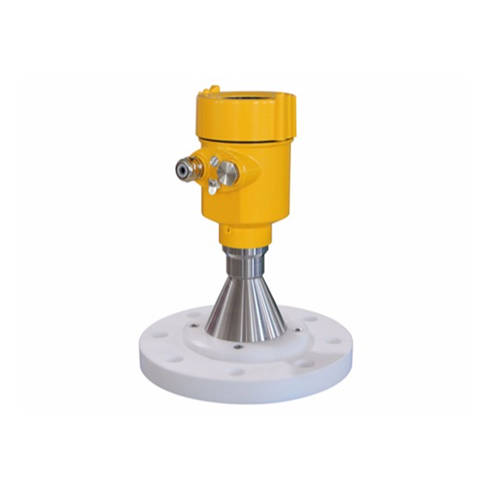
I. Core Reasons Behind the Continued Growth in Explosion-Proof Radar Level Meter Sales
Explosion-proof radar level meters have become a mainstream preferred choice for engineering projects and EPC contractors, mainly because of their technical advantages under complex and demanding operating conditions:
Outstanding resistance to environmental interference: High-frequency microwave signals such as 26GHz / 80GHz are used, and the measurement process is completely unaffected by vacuum, high concentrations of smoke and dust, intense steam, inert gases, extreme pressure, and high-temperature variations.
Explosion-proof safety redundancy: Flameproof (Ex d) or intrinsically safe (Ex ia/ib) certifications allow safe deployment in hazardous areas containing flammable and explosive gases, such as chemical tank farms, or combustible dust, such as coal silos and cement silos.
High sensitivity and stable signals: Based on intelligent echo analysis technology, the instrument can still accurately identify the true liquid level echo in low-dielectric-constant media or complex process vessels with agitators.
No mechanical wear and low maintenance: The non-contact design completely avoids material adhesion, mechanical wear, and mechanical jamming, significantly reducing on-site shutdown and maintenance costs.
II. Main Types of Radar Level Meters and Selection Comparison
| Selection Dimension | Low-Frequency Radar (6GHz - 10GHz) | High-Frequency Radar (26GHz / 80GHz) | Guided Wave Radar |
|---|---|---|---|
| Beam Angle and Focusing | Wide transmission angle, with energy easily dispersed | Extremely narrow beam, as small as 3°, with strong focusing capability | Directional transmission along a cable or probe rod |
| Applicable Operating Conditions | Conventional calm liquid surfaces and simple large storage tanks | Heavy dust, confined spaces, tall tanks, and vessels with agitators | Heavy foam, extremely low dielectric constant, and very narrow tanks |
| Antenna Type | Horn antenna | PTFE anti-condensation antenna, planar / parabolic antenna | Cable or rod probe |
| Resistance to Dust and Steam | More susceptible to interference | Extremely strong (strong penetration capability with air purging) | Completely unaffected by the gas phase and steam |
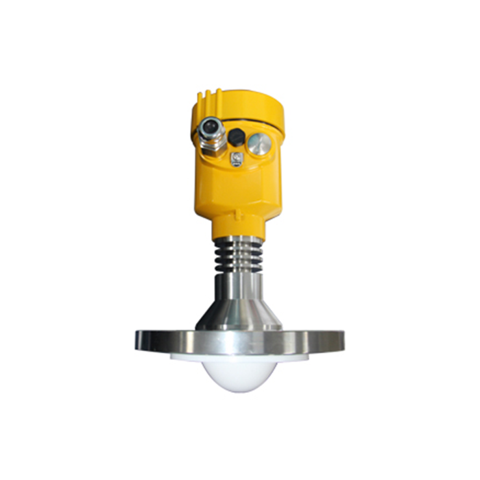
III. Key Radar Level Meter Selection Factors and Resolution Standards
1. Key Parameter Matching
Dielectric constant (εr): For low-dielectric-constant media such as diesel and liquefied gas, 80GHz high-frequency radar or guided wave radar with a cable probe should be prioritized to ensure sufficient reflected echo strength.
Process temperature and pressure: For high-temperature conditions above 200℃ or high-pressure applications, cooling extensions, ceramic seals, and high-grade flanges should be configured.
Corrosion-resistant and dust-resistant design: PTFE fully sealed antennas should be selected for strong acids and alkalis. For high-dust or crystallizing conditions, such as clinker silos, a parabolic antenna with an instrument-air purging interface should be selected.
2. Industrial Resolution and Accuracy Standards
| Instrument Grade | Resolution Range | System Measurement Accuracy | Typical Applications |
|---|---|---|---|
| Industrial Process Grade | 10 mm – 20 mm | ±2 mm – ±5 mm | Reactor control, cement / coal silo level monitoring, and intermediate process tanks |
| Custody-Transfer Grade | Within 1 mm (up to 0.1 mm) | ±0.5 mm – ±1 mm | Commercial oil terminals and custody transfer of high-value fine chemicals |
IV. Technical Requirements for High-Frequency Radar Level Meter Flange Installation
The flange is the core sealing connection between the radar level meter and the process vessel. High-frequency radar level meters can provide measurement distances of up to 30 meters, and the installation orientation of the flange directly determines the microwave beam path and echo quality.
1. Orientation Rules for Flange Reference Marks
The flange is marked with an orientation reference, which must be correctly aligned when the bolts are tightened:
Conventional storage tank installation: The flange reference mark should accurately point toward the tank wall or the geometric center of the storage tank so that the microwave beam avoids internal obstacles.
Stilling Well installation: The flange reference mark must point toward the side containing the stilling-well opening, such as an equalization hole or vent hole.
Bypass Chamber installation: The flange reference mark must point toward the side containing the upper and lower connecting pipes linked to the storage tank.
2. Physical Flange Rotation and Interference Echo Optimization
Signal diagnostics: If the echo amplitude is low or background noise is high during commissioning, this indicates that the microwave beam may be affected by internal tank structures.
Step-by-step rotational adjustment: The flange bolts can be loosened and the flange rotated clockwise or counterclockwise by one bolt-hole position at a time. Observe the P003 echo curve on the commissioning interface until the interference echo amplitude is minimized. A reduction of more than 12 dB in the interference peak is recommended.
False Echo Suppression: Use the instrument's built-in “False Echo Learning and Storage” function to store reflections from fixed metal structures in the suppression mask and achieve the optimum measurement condition.
3. Flange Connection and Sealing Requirements
Threaded connection flanges can be used under low-pressure conditions. When the process pressure exceeds 0.4 MPa (approximately 4 bar), welded flanges, including slip-on or butt-weld flanges, must be used.
A sealing gasket compatible with the corrosion characteristics of the medium should be installed between the two flange faces, and all bolts should be securely tightened. The inner wall of the high-frequency radar mounting nozzle must be smooth, and the bottom of the antenna must extend at least 10 mm beyond the nozzle.
V. METRAVON System Integration and Compatibility Advantages
As a professional industrial automation instrumentation supplier, METRAVON high-frequency explosion-proof radar level meters are optimized for complex industrial operating environments:
Multi-protocol communication: Native support for 4–20mA + HART and RS-485 (Modbus RTU), with optional expansion to PROFIBUS-PA and FOUNDATION Fieldbus.
Seamless DCS/SCADA integration: Complete DTM/EDD driver files are available for direct integration with mainstream DCS control systems from Honeywell, Yokogawa, Schneider, Siemens, and third-party tank farm management platforms.
Industrial-grade reliability: Flameproof (Ex d) and intrinsically safe (Ex ia) certifications are available, together with built-in electromagnetic compatibility (EMC) protection and surge protection to ensure long-term stable operation in demanding electrical environments.
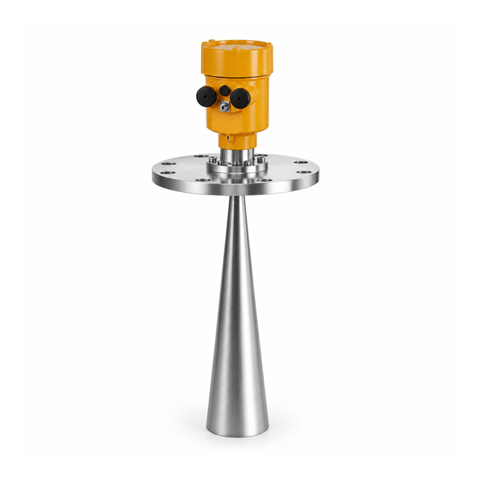
FAQ
Q1: How Should Dust Accumulation on the Antenna Be Handled in a Cement Silo with Extremely Heavy Dust?
A METRAVON 80GHz explosion-proof radar level meter is recommended, together with a dust cover and Air Purging flange interface. Instrument air at 0.2–0.4 MPa can be introduced periodically to purge the antenna surface and prevent dust accumulation.
Q2: Why Can Rotating the Flange Bolt Position Effectively Reduce Interference Echoes?
High-frequency radar microwaves have polarization characteristics. Rotating the flange changes the angle of the microwave polarization plane, reducing the reflected energy from internal tank obstacles such as ladders and agitator blades and thereby lowering the intensity of false echoes.
Q3: What Are the Selection Advantages of 80GHz Radar Compared with 26GHz Radar?
80GHz radar has a narrower beam angle, which can be as small as 3°, and highly concentrated energy. It can more easily avoid complex internal tank obstacles. Its antenna is also smaller, allowing installation on smaller-diameter mounting nozzles.
Q4: How Can a Radar Level Gauge Maintain Stable Measurement in a Reactor with Severe Agitation?
A high-frequency radar equipped with dynamic false echo suppression can be selected, or a Stilling Well can be installed to physically isolate the microwave beam from scattering interference caused by severe liquid-surface turbulence.
Q5: How Can “Flameproof” and “Intrinsically Safe” Explosion Protection Be Distinguished for Explosion-Proof Radar Level Meters?
Flameproof protection (Ex d) uses a high-strength enclosure to contain any sparks that may be generated by the internal circuitry. Intrinsically safe protection (Ex ia) limits circuit energy so that it cannot ignite hazardous gases or dust even under fault conditions. Selection should be made strictly according to the hazardous area classification, such as Zone 0/1/2 or Zone 20/21/22.
Conclusion
With the advantages of non-contact measurement, high accuracy, high explosion-proof safety redundancy, and strong adaptability to demanding operating conditions, explosion-proof radar level meters have become benchmark products in industrial level measurement. Strictly following flange orientation requirements, matching the appropriate selection parameters, and performing echo storage and adjustment are key to ensuring long-term stable system operation.
As a professional partner in industrial automation, METRAVON is committed to providing global system integrators and engineering contractors with stable, compatible, and easily scalable radar level measurement equipment and technical support.
Project Selection and Technical Support
Need METRAVON radar level meter 3D CAD installation drawings, Modbus register address tables, or a customized quotation for your specific operating conditions?
Contact the METRAVON engineering technical team for one-on-one professional selection support!
