


 Chinese
 Spanish
 Russian
 Portuguese
 French
 German
 Indonesian
 Thai
 Vietnamese
 Arabic
 Italian
 Turkish
 Polish
 Japanese


A guided wave radar measurement error should be described by its pattern before anyone changes damping or replaces the probe. A fixed offset, an error that grows with level, a sudden jump and a correct local reading with an incorrect PLC value point to different investigations. Treating all four as weak-echo problems can hide the fault and make the original settings difficult to recover.
Preserve the evidence before adjusting settings
Save the current configuration, instrument identity and a timestamped record of the complaint. Capture the local reading, receiving-system reading and independent reference at the same time where practical. Note filling, emptying, agitation, product change or cleaning activity. A screenshot showing only one unexplained number is a weak basis for diagnosis.
Use the documented reference plane for the selected instrument. A flange face, vessel roof and probe end are not interchangeable datums. Verify that the independent reference measures the same surface and that it remains trustworthy; a restricted sight-glass connection can create its own disagreement with the tank.
Classify the guided wave radar measurement error
| Pattern | First comparison | What it helps separate |
|---|---|---|
| Offset | Distance reference, level zero and independent readings at more than one level. | A reference error from a changing process effect. |
| Slope | Sensor range settings and receiving-system scaling across the working interval. | A span or conversion issue from a constant zero shift. |
| Jump | Event time, available echo information and process activity. | A changed target or installation disturbance from a gradual level change. |
| Host only | Local value, transmitted value and PLC or RTU interpretation. | A signal or decoding error from the measurement inside the instrument. |
These patterns are clues, not automatic fault codes. For example, a fixed wrong value can result from a retained last reading as well as a fixed reflection. Check validity or fault information where available before treating the displayed value as a current measurement.
Separate distance, level and output scaling
For a simple top-mounted arrangement, level equals the configured empty-reference distance minus measured distance to the surface. If that reference is wrong, a good distance measurement can still produce the wrong level. Changing a receiver's scale to compensate may make one operating point look right while obscuring the underlying cause.
Use at least two suitable known states when assessing zero and span. As a hypothetical diagnostic example, errors of +50 mm at both reference levels suggest a different investigation from errors of +50 mm at one level and +150 mm at another. Neither pattern proves a cause, and these values are not acceptance tolerances for METRAVON equipment.
If the local level agrees with the reference but the host does not, inspect the output path. For analog acquisition, compare the configured endpoints and input scaling. For digital acquisition, confirm the selected value and units against the instrument's data documentation. Do not change probe parameters to repair an error introduced after transmission.
Check the usable probe interval and its physical condition
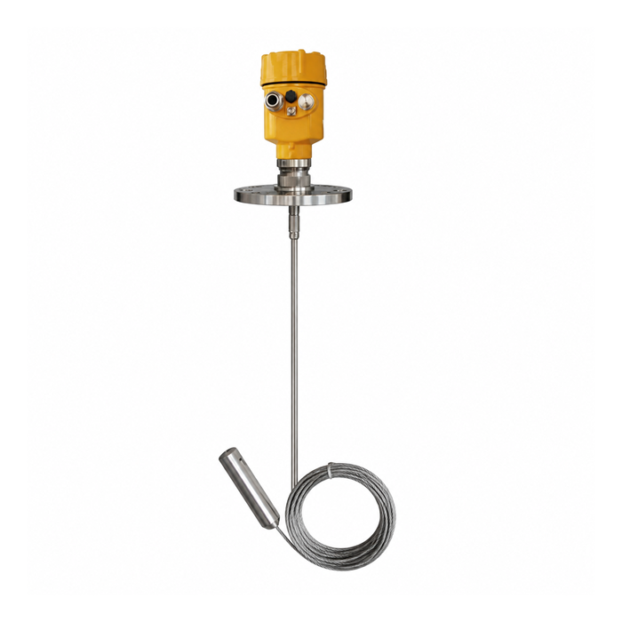
METRAVON MV-RD701 uses a contacting rod or cable arrangement. Its installation documentation identifies upper and lower non-measuring regions. The working liquid interval must be checked against the selected probe configuration; total probe length is not the same as a fully usable measuring span.
A fault that appears only near the top or bottom deserves particular attention to those limits. Do not extend a configured range into an excluded region merely to make the displayed scale match the vessel height. Confirm the permitted arrangement with the supplier if the process must operate closer to either end.
Physical inspection, when safely permitted, should address deposits, deformation, unintended contact and cable movement. Compare the present condition with the commissioning record. Any change to a probe, weight or restraint requires an approved configuration review. The guided-wave installation article provides the mechanical selection context.
Use echo information to test a hypothesis
Where diagnostic access is available, record the echo trace with the corresponding process state rather than treating the largest peak as an unquestionable surface. A feature that stays at one distance while the known level moves deserves investigation as a fixed reflection. A changing trace after cleaning is useful evidence of deposit influence, but the before-and-after levels must also be recorded.
Do not overwrite an existing suppression map or apply a generic threshold adjustment without the applicable commissioning procedure. A setting made while the surface position is unknown can suppress useful information. Preserve the original configuration and change one justified parameter at a time so the effect can be evaluated.
When the problem follows a product change, review the medium's electrical properties, foam and coating behaviour. A probe that performs with one liquid is not automatically qualified for another. Nor does the guided-wave principle establish that the selected model supports the interface between two liquids.
Troubleshooting questions
Q1. Should increasing damping be the first response to jumps?
No. First determine whether the instrument is tracking the intended surface and whether the probe remains correctly installed. Filtering can smooth a bad reading while delaying a real change. Adjust it only after the cause and the required response have been considered.
Q2. Is a clean, undamaged probe enough to rule out an installation issue?
No. Its clearance, position, usable interval and connection geometry can still be wrong. Review the drawing and actual mounting against the selected probe instructions, especially after vessel modifications or a replacement.
Q3. Can the instrument be verified without completely filling the tank?
Suitable known-level checks can provide useful evidence over the tested interval, subject to the approved procedure and a reliable reference. They do not demonstrate untested operating extremes. Record the coverage of the test rather than claiming full-range verification from one accessible point.
Q4. When is replacing the sensor justified?
Replacement becomes a supported decision when evidence identifies a defective or unsuitable instrument or probe configuration. If the problem is the host scale, a blocked chamber connection or an incorrect reference, an identical replacement may reproduce it. State which fault the replacement is intended to resolve.
Q5. What should a useful fault report contain?
Include the exact model and probe, configuration backup, drawing, simultaneous local and host readings, reference method and event history. Add available diagnostic traces and photographs obtained under safe conditions. Send the evidence for an MV-RD701 technical review with the conditions under which the fault can be reproduced.
Summary
Locate the error in the measurement chain before choosing a remedy. Preserve the settings, compare references and signals, then investigate probe condition and echo behaviour where the evidence points. Retest the original fault condition after a correction; a quiet display during an unrelated operating state is not verification.
