


 Chinese
 Spanish
 Russian
 Portuguese
 French
 German
 Indonesian
 Thai
 Vietnamese
 Arabic
 Italian
 Turkish
 Polish
 Japanese



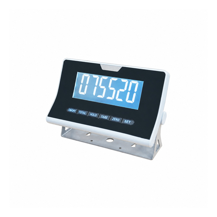
METRAVON MV-WI0010 is a large-display weighing indicator with a six-digit 50 mm display reference and 5 V load-cell excitation. It accepts a -6 to +19.5 mV analogue signal and lists drive capability for one to four 350-ohm sensors. Use the larger digits to address a defined operator viewing position, while checking the sensor circuit and data interface independently. It is not merely a remote repeater for another indicator.
Position the large-display weighing indicator for the real viewing angle
Record the operator position, ambient light, mounting height and any obstructions. Choose the actual LED or backlit LCD configuration rather than expecting the reference photograph to establish all display versions. A 50 mm digit height does not supply a guaranteed viewing distance, daylight contrast or ingress rating. Check a representative display at the intended location where those conditions are important. Leave access to keys and cable connections without placing the instrument in an unconfirmed washdown or weather exposure.
Distinguish direct sensor acquisition from a second-display connection
The main reference input is an analogue bridge signal, with 5 V excitation for the connected sensors. An optional RS232 interface can support a separately defined communication or second-display task, but a serial port is not interchangeable with the millivolt input. State whether the unit will acquire a scale directly or exchange a weight value with another device. Have the offered wiring and operating mode confirmed before reusing an existing indicator-to-display cable.
Review optional dual-input and network requirements explicitly
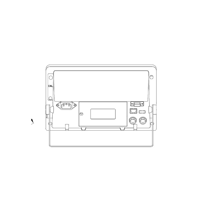
The reference describes optional serial, BLE, USB, Ethernet and dual-sensor-interface arrangements. It does not establish that one base unit includes all of them or explain every combined operating mode. A dual-interface description alone does not establish simultaneous independent weight displays, a summing function or a maximum sensor count beyond the stated configuration. Request the channel behaviour and data format needed by the project. For a PLC or data logger, agree the actual interface and content rather than assuming a network socket establishes a particular protocol.
| Item | Value | Selection notes |
|---|---|---|
| Display reference | Six-digit / 50 mm | LED or backlit LCD configuration to be identified in the offer. |
| Bridge input / excitation | -6 to +19.5 mV / 5 V DC | Not a serial-repeater input; check the actual acquisition task. |
| Reference drive | One to four 350-ohm cells | Optional dual-interface behaviour requires separate confirmation. |
| Display / internal counts | 15,000 / 1,000,000 | Set and verify a useful scale division instead of treating counts as accuracy. |
| Front-width reference | 270 mm | Use the selected enclosure drawing for bracket fit or panel work. |
| Battery runtime reference | 100 hours with four 350-ohm sensors | Require the battery and display conditions for the offered configuration. |
Check the battery statement against the selected display
The supply reference includes AC 110/220 V at 50/60 Hz and a specified internal battery, with a 100-hour continuous-use figure under a four-sensor 350-ohm load. Obtain the actual display, battery and accessory conditions behind the offered runtime. Do not assume that every bright LED and wireless configuration has the same consumption as an unspecified reference arrangement. Check mounting support and the released enclosure drawing as well: the reference front width is 270 mm, but it is not a universal panel cut-out dimension.
Verify what the distant operator sees and records
Calibrate the scale under the agreed procedure, then check readings and status indications at the intended observation position. Confirm units, gross or net selection and whether a hold function can leave an old value visible. The listed 15,000 display counts and 1,000,000 internal counts are not a total measurement-accuracy statement. Compare repeat readings and unloading return, then verify any serial, printed or network result against the displayed measurement. Record the fitted options so a later replacement does not become an interface guessing exercise.
For a different large-display power and bridge arrangement, compare the MV-WI0011 3.3 V excitation and battery requirements. The shared input endpoints do not make the two configurations electrically identical.
Visibility, repeaters and optional acquisition modes
Q1. Is the larger display a reason to select a finer weight division?
Digit size affects visibility, not sensor signal, noise or installed weighing performance. Choose the division from the measurement requirement and verify it with the complete scale.
Q2. Can an existing serial repeater cable be connected to the load-cell input?
No. The bridge input receives the specified millivolt signal and provides excitation. Any serial link must use the confirmed communication option with the correct electrical connection and message format.
Q3. Does the optional Ethernet interface mean Modbus TCP is included?
The available interface description does not establish that protocol. Obtain the supplied network function and documentation for the receiving system before approving integration.
Q4. Does a dual-sensor option guarantee two independent channels?
The measurement and display behaviour must be defined for the offered version. Ask whether the required independent acquisition, switching or calculation is supported, and confirm sensor loading and outputs in that configuration.
