


 Chinese
 Spanish
 Russian
 Portuguese
 French
 German
 Indonesian
 Thai
 Vietnamese
 Arabic
 Italian
 Turkish
 Polish
 Japanese



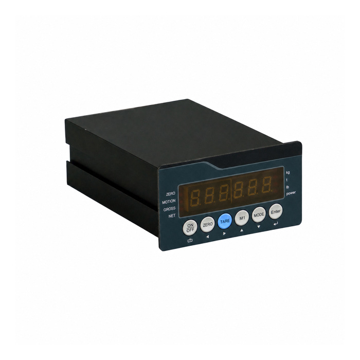
METRAVON MV-WI0009 is a weighing controller for filling, dosing and hopper-weighing equipment. It provides four relay outputs and four optically isolated switch inputs, with RS232/RS485 serial communication. Specify the required Modbus RTU and 4-20 mA options explicitly; the presence of these functions in the product family does not establish the configuration of a quoted unit.
Decide which device controls the weighing cycle
A PLC may supervise the sequence while the weighing controller supplies weight and discrete signals. Alternatively, the project may use more of the controller's local functions. Before choosing, write down the required start, stop, feed, discharge and fault responses. Have the available controller functions checked against that sequence; four relays do not by themselves establish a complete batching program.
| Connection or function | Published capability |
|---|---|
| Analog load-cell input | -3 to 30 mV |
| Excitation and sensor wiring | 5 V DC; 6-wire |
| Bridge drive capacity | 1-8 analog sensors, 350 ohm each |
| Relay outputs | 4 |
| Switch inputs | 4, optically isolated |
| Serial connection | RS232/RS485; 600-9600 bit/s selectable |
| Modbus RTU | Confirm this option and the applicable register map with the order. |
| Analog output | 4-20 mA, optional |
| Supply versions | 220 VAC, 50/60 Hz; or 24 VDC |
The input can support the stated number of sensors in a weighing assembly; this is not a claim of eight independent weight channels. Check the combined bridge load and six-wire connections against the installation diagram. For multi-support scales, the junction-box adjustment guide explains how channel balancing differs from the controller's overall scale calibration.
Specify the relay implementation and switch-input circuit
Four relay outputs are listed, but the English description specifies solid-state relays while the Chinese description does not identify the relay technology. Obtain the supplied output circuit and electrical ratings before assigning a contactor, valve or PLC input. Where the output is solid-state, check the permitted AC or DC load, polarity, off-state leakage and switching limits in the supplied documentation. Do not assume a volt-free mechanical contact. The four optically isolated inputs also need their own voltage and wiring specification; isolation does not establish a 24 V input rating.
Resolve shared ports and output scaling
The printer connection shares the serial interface. If a PLC, printer and remote display are all required, ask for the actual port allocation and supported operating modes. Do not order on the assumption that every listed function can run simultaneously through separate connectors.
For Modbus RTU, confirm the register addresses, data representation, units and command permissions before writing the PLC program. For the optional current output, agree which weight values correspond to 4 mA and 20 mA, then check the PLC's scaled reading at intermediate loads as well as the endpoints.
The controller has a six-digit 10 mm LED display and a listed display resolution of 30,000 divisions. Its operating limits are -10 to +40 C and up to 85% RH. Those figures do not define a cabinet protection rating or a guaranteed filling tolerance.
Control-system questions
Q1. Can a relay output switch a feeder motor directly?
Obtain the output circuit and switching ratings, including the permitted load type and starting or switching conditions. The four-output count cannot approve a direct motor connection. Have the machine designer select any contactor or interposing device and a separate protective circuit; do not assume that a solid-state output behaves like a mechanical dry contact.
Q2. What should a filling trial verify?
Use the real material and feeder to compare the controller indication, cutoff response and final settled weight. Include restart and interrupted-feed cases under an approved test procedure. Agree the acceptance tolerance and fail response for the machine; the indicator's resolution cannot predict material still falling after cutoff.
Q3. Can the same controller accept either mains or 24 V DC without checking?
The catalogue lists alternative supplies. Select the required version and verify its nameplate and terminal diagram before energising it. Do not treat an AC/DC listing as permission to connect either source to an unidentified unit.
Q4. Does a 24 V controller supply establish the switch-input voltage?
No. The supply version and the optically isolated input circuit are separate specifications. Request the input voltage limits, terminal common, active state and source or sink arrangement before wiring a PLC output or field switch. Verify the intended start, stop and fault responses with the approved circuit.
For an MV-WI0009 quotation, provide the sensor load, control sequence, I/O assignments, supply choice and PLC interface. List Modbus RTU, current output and printing separately so that the offered hardware and documentation can be checked against the machine design.
