


 Chinese
 Spanish
 Russian
 Portuguese
 French
 German
 Indonesian
 Thai
 Vietnamese
 Arabic
 Italian
 Turkish
 Polish
 Japanese



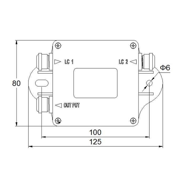
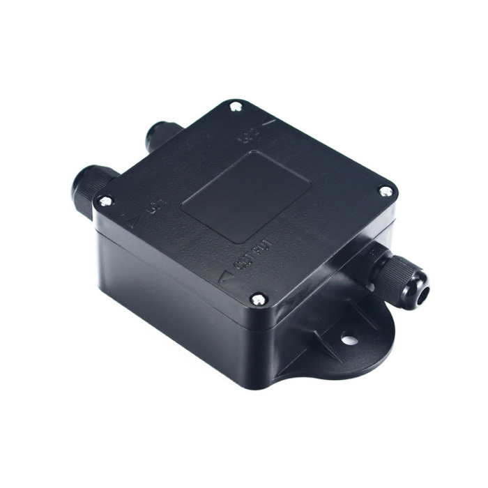
METRAVON MV-WI0014 is a 4-20 mA weighing transmitter for one 350 ohm analog load cell. It accepts a rated sensor output of 1-3 mV/V and provides 5 V excitation. Use it where a PLC or other receiver needs an analog weight signal, provided the project's error allowance is compatible with the listed 1% linearity specification.
Check the current output and receiver load together
| Electrical specification | MV-WI0014 |
|---|---|
| Output | 4-20 mA configuration |
| Power supply | 8-30 V DC |
| Receiver load | Typical 250 ohm; listed range 0-500 ohm. Below 10 V DC, permissible load is reduced. |
| Load-cell drive | One 350 ohm analog sensor |
| Excitation voltage | 5 V |
| Sensor rated output | 1-3 mV/V |
| Listed linearity | 1% |
| Zero range | 4 mA +/-0.2 mA |
| Adjustment | Potentiometer adjustment of zero and linear output |
| Operating temperature | -10 to +40 C |
Do not combine the lowest supply voltage with the maximum listed receiver resistance without checking the permitted operating point. Include the receiver input resistance, cable and any additional devices in the circuit review. Obtain the transmitter terminal diagram to establish its supply and signal wiring; a 4-20 mA output does not by itself identify a two-wire, loop-powered device.
Calibrate weight and current as one measurement chain
Define the physical load assigned to each output endpoint before adjustment. Apply appropriate reference loads to the installed sensor, set the transmitter according to its adjustment instructions, and configure the PLC to use the same endpoints and units. Check intermediate loads and the return to zero as well as the span.
For example, a 2 mV/V sensor excited at 5 V has a nominal rated output of 10 mV. This is a signal calculation, not a statement of scale capacity or calibration accuracy. The load-cell capacity, actual loading and mounting arrangement still determine how the electrical input relates to weight.
The stated 1% is a linearity figure, not a guaranteed total weighing error. Its reference basis and test conditions must be confirmed before using it in an error budget. Do not relabel it as 0.1%, convert it into an unsupported mass tolerance or assume that adding a high-resolution PLC input improves the transmitter's linearity.
Analog transmitter questions
Q1. Can a junction box extend this transmitter to four load cells?
The published drive rating is for one 350 ohm sensor. A junction box combines wiring but does not increase the transmitter's excitation capacity. Use a device rated for the required combined bridge load, or obtain explicit electrical approval for another arrangement; do not treat the number of enclosure entries as a sensor-drive rating.
Q2. Is serial weight data available from this model?
This specification covers the current-output configuration, not an RS232 or RS485 data port. For a command-based serial connection to one load cell, review MV-WI0015 and check its different supply versions and command requirements. The two models are not electrically interchangeable merely because their enclosures look similar.
For MV-WI0014 pricing and suitability review, supply the sensor resistance and rated output, required load span, available DC voltage, receiver input specification and acceptable system error. Confirm the 4-20 mA configuration and wiring documentation in the quotation before purchasing the transmitter.
