


 Chinese
 Spanish
 Russian
 Portuguese
 French
 German
 Indonesian
 Thai
 Vietnamese
 Arabic
 Italian
 Turkish
 Polish
 Japanese



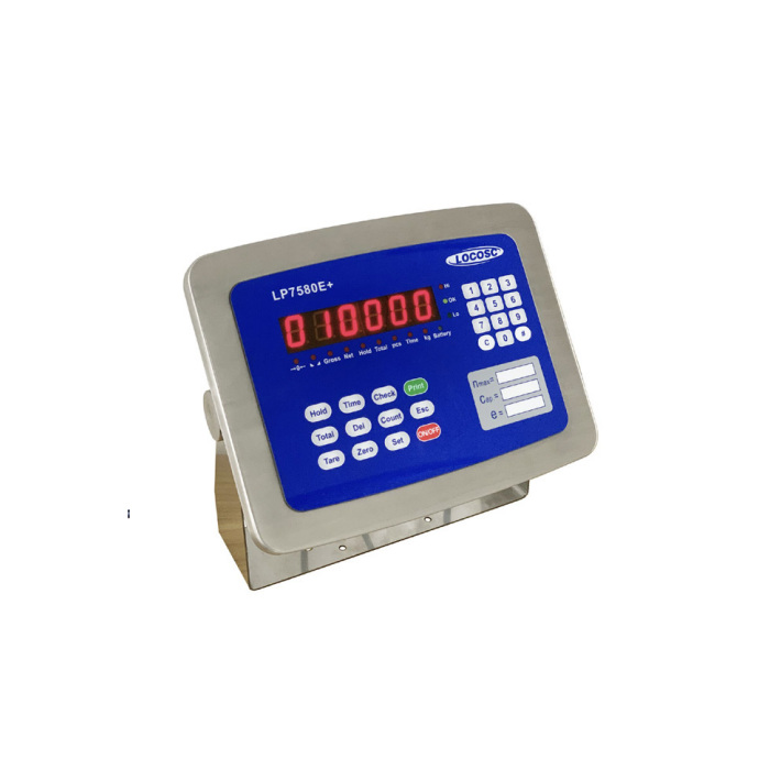
METRAVON MV-WI0012 is a keypad weighing indicator with a six-wire load-cell interface, 5 V bridge excitation and a reference drive capability of one to twelve 350-ohm sensors. Its input interval is -3 to +20 mV. The numeric keypad, clock and multiple communication descriptions make it a candidate for recorded weighing tasks, but the offered port configuration and input circuit must be defined before PLC, DCS or computer integration is approved.
Describe the keypad weighing record before specifying the ports
Identify the values the operator must enter or select and the result that must be retained. The reference includes a clock, dated printing, counting, accumulation and hold functions, but it does not establish a customer-specific database, user permission scheme or unlimited transaction memory. Have the actual input sequence, print fields and result handling demonstrated for the offered configuration. Decide how an incorrect entry, changed tare or held value will be recognised in the operating procedure.
Use six-wire sensing with the approved terminal schedule
Six-wire sensing and a twelve-sensor drive reference do not mean twelve independent acquisition channels. Give the sensor count, sensitivity, resistance and junction arrangement and obtain the actual excitation, sense and signal connections. Confirm how the cable and junction equipment preserve the required sensing path. If the existing scale uses four-wire sensors, request the supported arrangement rather than linking unspecified terminals by assumption. Check the total tare and working signal against the input interval before choosing a fine display division.
| Item | Value | Selection notes |
|---|---|---|
| Analogue input / excitation | -3 to +20 mV / 5 V DC | Include tare, offset and working signal in the input check. |
| Load-cell interface | Six-wire reference | Require the supplied terminal schedule and any approved four-wire adaptation. |
| Drive capability reference | One to twelve 350-ohm sensors | Sensor-drive limit; not twelve separate weight channels. |
| Display reference | Six-digit 20 mm LED / 30,000 counts | Internal-count notation differs between references; obtain a confirmed performance schedule. |
| Communication description | Three RS232 / one RS485 / USB COM | Confirm fitted ports, isolation, simultaneous use and command documentation. |
| Optional process outputs | Relay / 4-20 mA configurations | Require electrical ratings, scaling and invalid-state behaviour for the actual option. |
| Battery runtime reference | 20 hours with four 350-ohm sensors | Do not extend that runtime to twelve sensors or every output configuration. |
Allocate serial, USB COM and printer functions explicitly
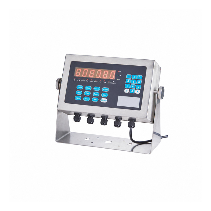
The reference describes three RS232 interfaces, one RS485 interface and one USB COM connection, with some isolation detail differing in the descriptions. Obtain the port schedule and isolation specification of the selected build. The printer interface is described as shared with serial communication, so map simultaneous printing, host commands and PLC or DCS traffic to actual available ports. USB COM is a serial communication function, not a promise of USB-stick logging. A command-mode interface is not automatically Modbus RTU; request the supported commands and response format.
Define optional control outputs and their safe operating role
Relay functions and 4-20 mA appear as options. Specify the fitted output, electrical ratings, weight scaling and the required state during startup, invalid readings and communication loss. The source descriptions do not establish one universal relay contact type or a safety-rated control function. If an output is used to supervise filling or sorting, verify its behaviour in the complete control scheme and keep any independent protective function separate. Do not assign process interlocks from a catalogue output symbol alone.
Confirm power and resolution without carrying over conflicting numbers
The references agree on a 6 V/4 Ah battery arrangement and give a 20-hour continuous-use reference with four 350-ohm sensors. They differ on the mains/DC description and format the internal converter-count figure inconsistently. Use the offered input rating and confirmed performance specification rather than reproducing an uncertain number. The 30,000 display-count reference and 1 microvolt-per-verification-interval minimum do not guarantee a legal-for-trade division or installed accuracy. Verify the agreed working increment, repeated loading, unloading return and the received or printed record with the final system.
For a smaller sensor count with separately selected controller interfaces, review the MV-WI0004 bridge and optional-output configuration. It has a different sensor-drive and input specification.
Six-wire sensing, USB COM and process outputs
Q1. Does twelve-cell drive provide twelve weight values?
It specifies the reference loading of the analogue sensor circuit. Independent weight channels need an explicit acquisition configuration; they are not established by the maximum number of driven sensors.
Q2. Can USB COM write a weighing log to a USB stick?
That description identifies a communication port, not mass-storage logging. Obtain the supported host connection and software or command interface for the required record workflow.
Q3. Can an RS485 connection be commissioned using a standard Modbus map?
Only if the offered version explicitly supports that protocol and supplies its map. The documented command mode and RS485 hardware alone do not establish Modbus compatibility.
Q4. Can the relay output replace an independent protective interlock?
No safety-rated function follows from the output option. Establish the required protective architecture separately and verify the actual output ratings and invalid-reading behaviour for its intended process role.
