


 Chinese
 Spanish
 Russian
 Portuguese
 French
 German
 Indonesian
 Thai
 Vietnamese
 Arabic
 Italian
 Turkish
 Polish
 Japanese



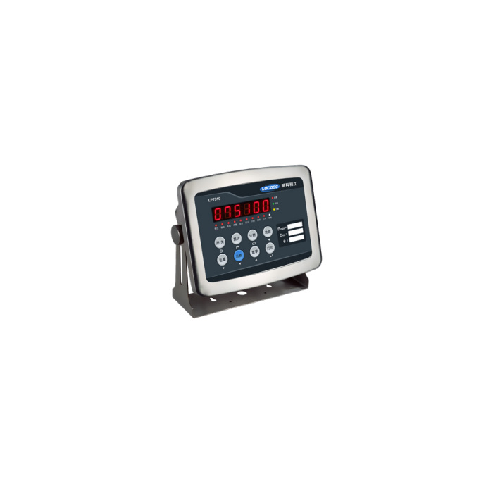
METRAVON MV-WI0004 is an analogue-load-cell weighing indicator for bench, platform and hopper-scale measurement. It provides 5 V bridge excitation with a reference drive capability of one to six 350-ohm sensors and a -5 to +20 mV input interval. Select the sensor circuit and required output options before choosing the displayed division. A large display count or a 24-bit converter does not, by itself, establish the accuracy of the installed scale.
Check the weighing indicator input against the complete bridge circuit
Give the sensor count, rated sensitivity, input resistance, wiring and cable arrangement. The reference is a four-wire connection, with a six-wire version listed as an option. Do not assume a delivered four-wire unit supports remote sensing simply because another enclosure in the family does. Compare the largest expected signal, including tare and offsets, with the input interval. For illustration, a 2 mV/V sensor excited at 5 V produces a nominal 10 mV rated signal; that arithmetic is not a guarantee of the usable resolution after installation.
| Item | Value | Selection notes |
|---|---|---|
| Sensor input interval | -5 to +20 mV | Account for tare signal and offsets, not only the normal net load. |
| Bridge excitation / drive | 5 V DC / one to six 350-ohm cells | Four-wire reference; six-wire connection is an option to confirm. |
| Display / internal counts | 50,000 / 2,000,000 | These do not establish installed accuracy or approved verification divisions. |
| Minimum signal reference | 1 microvolt per verification interval | Check actual signal per division and stability at the selected range. |
| Display alternatives | 20 mm LED / 25 mm LCD | Six digits; select the actual display and backlight configuration. |
| Optional interface examples | RS485, Modbus RTU, 4-20 mA | Require the fitted combination, wiring and protocol or scaling document. |
Separate display resolution from verified weighing performance
The reference lists 50,000 display counts, 2,000,000 internal counts and a minimum signal of 1 microvolt per verification interval. Those are different specifications. Selecting more displayed divisions can reveal noise or instability without improving the physical measurement. The stated class and verification-division reference likewise must not be treated as a certificate for every branded configuration or completed scale. Establish the required working range, minimum useful increment and any legal-metrology approval with the actual offered hardware and documentation.
Order the PLC output and check which ports are shared
RS232, RS485, 4-20 mA, relay functions and expandable protocols including Modbus RTU and Modbus TCP are listed as configurations or options. They are not a declaration that every connector and protocol is fitted together. The printer connection shares the serial interface, so identify whether printing, a remote display and controller communication must operate simultaneously. Obtain a terminal schedule, protocol description and the offered combination. For a PLC or RTU, agree gross or net value, units, status handling and the mapping of weight to the selected output.
Choose the display and power arrangement for the operator position
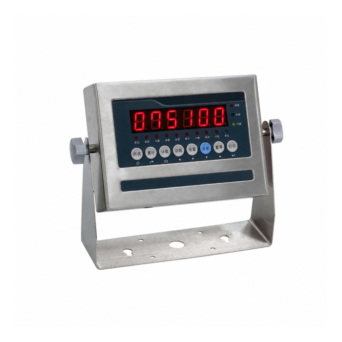
The display alternatives are six-digit 20 mm LED and 25 mm backlit LCD. The reference power arrangements include AC 110-240 V at 50/60 Hz, DC 9 V and specified internal batteries. Identify the actual version, power input and charging arrangement before installation. A 30-hour continuous battery reference is stated with four 350-ohm sensors; do not extend that duration to six sensors or added communications equipment without confirmation. Also check mounting visibility, cable access and environmental limits rather than assuming a waterproof scale application establishes the enclosure IP grade.
Verify the value received by the controller, not only the front display
After calibration with an agreed independent weight reference, compare zero, several working loads and unloading return at the indicator and receiving equipment. Check the selected tare behaviour and the conditions under which the receiver should accept a reading. Where a current output is ordered, verify its scaling; where a protocol is ordered, verify the value and relevant status information using the supplied documentation. Do not invent an update rate or register map from the port name. Keep the fitted option list and calibration settings with the scale record.
For a four-cell scale without the broader option requirement, compare the MV-WI0005 input and serial-printing requirements. Its input interval, sensor drive and interface offer differ.
Sensor drive, fitted interfaces and verification
Q1. Does six-cell drive mean six independent measurement channels?
It describes the stated analogue bridge drive capability, not six separately acquired channels. Confirm the actual connection and junction scheme; do not expect individual sensor readings unless that function is explicitly supplied.
Q2. Are Modbus RTU and 4-20 mA included with every unit?
They are listed as optional or expandable configurations. Specify the outputs needed and obtain the offered hardware combination and documentation. Do not approve integration from an unqualified list of available options.
Q3. Can the printer and PLC use the same serial connection simultaneously?
The reference says the printer connection is shared with the serial interface. Have the required simultaneous functions and port allocation confirmed; the presence of a print key does not establish an additional independent port.
Q4. Does the displayed count prove legal-for-trade approval?
No. The offered indicator configuration and completed scale need the applicable approval and verification documents for that use. Display counts, internal converter counts and verification divisions are not interchangeable claims.
