


 Chinese
 Spanish
 Russian
 Portuguese
 French
 German
 Indonesian
 Thai
 Vietnamese
 Arabic
 Italian
 Turkish
 Polish
 Japanese



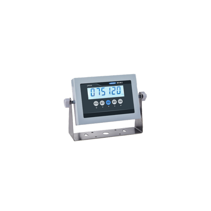
METRAVON MV-WI0005 is a four-wire weighing indicator intended for bench, platform and hopper-scale installations. Its reference input interval is -10 to +19.5 mV, with 5 V excitation for one to four 350-ohm analogue load cells. For a replacement, identify the existing sensor circuit and the operator workflow before retaining the old cable or selecting a visually similar enclosure. The display, battery and printing configuration also need to be specified.
Identify what the operator must record or print
State whether the scale is used for a single stable weight, accumulation or a check-weighing sequence, and what record the operator needs. Serial printing is an option rather than evidence that every indicator includes a printer mechanism. The reference printer connection shares the serial interface. Have the requested print format, connected printer type and any simultaneous remote-display or data collection function confirmed before purchase. A serial connector does not establish compatibility with every existing printer or application.
Retain the four-wire sensor connection only after electrical checks
Compare sensor count, resistance and rated signal with the indicator input and drive capability. Four 350-ohm cells are the stated upper reference, not permission to attach any number of high- or low-resistance sensors. Give the junction-box arrangement and actual cable functions, particularly if the old indicator used sense leads or a modified connector. The -10 to +19.5 mV interval allows a signal range, not an automatic correction for reversed wiring, an overloaded cell or an unintended mechanical preload.
| Item | Value | Selection notes |
|---|---|---|
| Bridge input interval | -10 to +19.5 mV | Check the complete signal, including tare and any zero offset. |
| Sensor connection / drive | Four-wire / one to four 350-ohm cells | Confirm the actual junction and connector wiring before reusing cables. |
| Bridge excitation | 5 V DC | Match the installed sensor requirements, not only its nominal capacity. |
| Display / internal reference | 15,000 / 1,000,000 counts | Minimum signal: 1 microvolt per verification interval; not a total accuracy statement. |
| Power alternatives | AC 110-240 V / DC 9 V / battery | Identify the actual battery and charging configuration. |
| Serial and printing configuration | RS232 option; shared serial printer link | RS485 wording differs between references; require explicit supplied-version confirmation. |
Do not infer an RS485 configuration from a serial label
The Chinese option description specifies RS232, while the English option description also mentions RS485. Identify the actual offered interface explicitly rather than resolving that difference by assuming both are installed. RS485 alone would not establish Modbus RTU support or a register map. Where data collection is required, obtain the electrical connection and message format for the supplied version and test it with the intended receiver. Do not transfer the broader protocol menu of a higher-option indicator to this model.
Choose the division and display without confusing them with accuracy
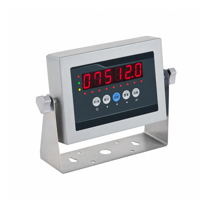
The reference is 15,000 display counts, 1,000,000 internal counts and a minimum 1 microvolt per verification interval. The class reference includes n = 5,000; it is not the same as the display count and is not a certificate for the complete installation. Specify the working load range and smallest useful increment, then verify stable readings with the actual load cells. The display choices are 20 mm LED or 25 mm backlit LCD, both six-digit; choose for the viewing conditions and actual enclosure offered.
Check power continuity and repeat the replacement calibration
The listed power arrangements are AC 110-240 V at 50/60 Hz, DC 9 V or a specified internal battery, with a 35-hour continuous reference under a four-cell 350-ohm load. Battery type, condition and configuration must match the offer before that figure is used for shift planning. After changing the indicator, recalibrate with the agreed weight reference and verify units, tare, repeat readings, unloading return and any printed result. Record the serial settings and cable assignment so that the next replacement is not based on appearance.
If the project needs six-cell drive or separately specified controller-output options, review the MV-WI0004 bridge and interface configuration. Confirm the complete offer rather than transferring its protocol list to this model.
Replacement wiring, printing and battery operation
Q1. Can a six-wire sensor cable be plugged in without further checks?
The reference connection is four-wire. Identify every cable function and obtain the permitted wiring arrangement for the supplied indicator. Do not assume spare connector pins are sense inputs.
Q2. Is the 35-hour battery figure a guarantee for every operating shift?
It is a reference for continuous use with four 350-ohm sensors. Confirm the delivered battery and operating configuration and assess practical reserve for the duty. Extra equipment or a different battery condition cannot be ignored.
Q3. What is required to connect existing weighing software?
Obtain the fitted serial interface, message format and settings and compare them with the software input. A matching baud rate alone does not establish compatible data, units or weight-status handling.
Q4. Should a new indicator retain the old span factor?
Use the calibration procedure for the supplied instrument and verify against an independent load reference. Settings from another indicator may not represent the same sensitivity, units or division, even if the scale mechanics are unchanged.
