


 Chinese
 Spanish
 Russian
 Portuguese
 French
 German
 Indonesian
 Thai
 Vietnamese
 Arabic
 Italian
 Turkish
 Polish
 Japanese



METRAVON MV-WI0001 is a wireless load-cell node that acquires an analogue scale signal and sends it to a matched MV-WI0003 receiver over Zigbee 2.4 GHz. The reference configuration has three LED status indicators rather than a numeric weight display. It can drive up to eight 350-ohm load cells. Specify it when the operator will read weight at the receiver; choose the LCD node instead if weight must also be visible beside the scale.
Place the wireless load-cell node between the scale circuit and receiver
The node replaces a defined wired acquisition link, not the mechanical weighing assembly. The load cells still need a suitable junction and cable arrangement at the scale. Give the cell resistance, sensitivity, number of cells and wiring diagram so the bridge connections and excitation can be confirmed. Eight-cell drive describes the supported sensor load on one circuit; it does not establish eight separately transmitted weights. A digital load-cell bus or a 4-20 mA transmitter cannot be substituted for the analogue bridge without a supported input configuration.
| Item | Value | Selection notes |
|---|---|---|
| Node indication | Three LED status lights | No numeric local weight display is listed. |
| Cell-drive reference | Up to eight 350-ohm cells | One scale circuit; not eight independent channels. |
| Wireless connection | Zigbee / 2.4 GHz | Pair with the specified receiver and radio version. |
| Distance reference | 80 m | Validate the actual route with all nodes operating. |
| Battery reference | 3.7 V / 4000 mAh | Capacity is listed in the Chinese edition. |
| Published endurance | 20 h / 40 h | Editions differ; require a confirmed duty and runtime. |
Order the matched radio pair, not an unspecified Zigbee device
The documented receiver for this node family corresponds to METRAVON MV-WI0003. Its reference arrangement accepts up to six matched nodes, which is a different limit from the cells driven by one node. List each scale and its intended receiver identity in the order. Sharing the Zigbee name and 2.4 GHz band does not establish pairing with an arbitrary gateway or an existing wireless scale. Obtain the supported radio version and pairing procedure before retaining a receiver from an older installation.
Size operating reserve from the offered battery configuration
The Chinese reference lists a 3.7 V/4000 mAh lithium battery and 40 hours of continuous operation; the English edition gives 20 hours for this LED-status version. Those statements do not support one unconditional runtime. Request the supplied battery capacity and the test duty behind the offered endurance, including the number of connected sensors and communication activity. Establish how the node is charged, removed or replaced between shifts. Receiver mains or battery specifications must not be copied into the node power schedule.
Check radio access and mounting before removing the old cable
The listed 80 m radio distance is a reference, not a guaranteed operating radius around steelwork or vehicles. Trial the proposed node and receiver positions with the actual obstructions and all required nodes active. Keep access to the battery connection, controls and sensor cable entries. The aluminium-alloy housing is described as sealed and moisture-resistant, but the available description gives no quantified IP grade or cleaning approval. Obtain the delivered enclosure limits before specifying outdoor exposure, immersion or pressure washing.
Prove channel identity and missing-data behaviour at handover
Load each scale individually and verify that the receiver attributes the change to the intended node. Then test the required combined operating sequence and compare results with the agreed reference loads. Interrupt one radio link and one node supply deliberately under a controlled commissioning procedure. Observe whether a value disappears, remains on screen or changes status, and agree how the operator detects incomplete data before using a total. No particular loss alarm, stale-data timeout or automatic recovery behaviour is established by the radio specification alone.
Compare MV-WI0002 for local LCD weight indication, or review the MV-WI0003 receiver and six-node arrangement when specifying a complete wireless scale.
Local readings and replacement-node orders
Q1. Can an operator read the weight directly on this node?
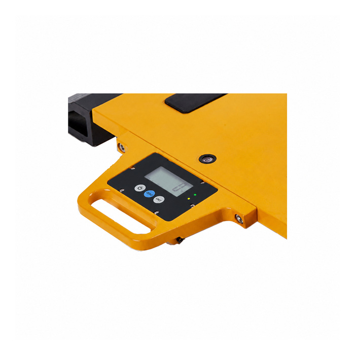
The documented MV-WI0001 indication consists of status LEDs. Use the matched receiver for the numerical reading, or specify MV-WI0002 when local LCD weight indication is required. The shared catalogue photograph shows the LCD variant and does not change the LED-version specification.
Q2. Can one node provide eight independent load-cell readings?
The eight-cell statement concerns electrical drive capacity on the scale circuit. For separately identified measurements, define the acquisition channels and supported node arrangement explicitly rather than equating connected cells with separate radio values.
Q3. What should an enquiry include for an existing wireless scale?
Send the receiver and node identification, radio version if known, load-cell data, junction wiring and required scale count. Include the working shift and intended radio route. The quotation should identify the matched equipment, battery arrangement and commissioning checks; a replacement node name alone is insufficient.
