


 Chinese
 Spanish
 Russian
 Portuguese
 French
 German
 Indonesian
 Thai
 Vietnamese
 Arabic
 Italian
 Turkish
 Polish
 Japanese



METRAVON MV-WA0011 is a single-shielded weighing signal cable for connections in a load-cell measurement circuit. The model identifies the shielding type; it does not, by itself, specify the number of conductors, their cross-section, cable length or connector arrangement. Those details must match the sensor, junction box and weighing instrument.
Specify the circuit before the cable length
A four-wire bridge connection and a six-wire connection with separate sense conductors have different wiring needs. Start with the terminal diagrams at both ends, including the shield or drain connection. Do not count the shield as an interchangeable signal conductor or copy wire colours from another manufacturer's cable.
| Enquiry detail | Why it matters |
|---|---|
| Conductors | The count and cross-section must suit the excitation, signal and any sense circuit. |
| Installed route | Include the actual run and service allowance. Electrical suitability must be checked at that length. |
| Cable diameter | Glands, connectors and strain relief must fit the finished cable. |
| Environment | State moisture, cleaning chemicals, temperature and whether the cable moves in service. |
There is no universal maximum run stated for MV-WA0011. Voltage drop, conductor resistance, the indicator's excitation limits and its sense arrangement can affect the acceptable length. A cable extension is therefore an electrical change, not just an order for extra metres.
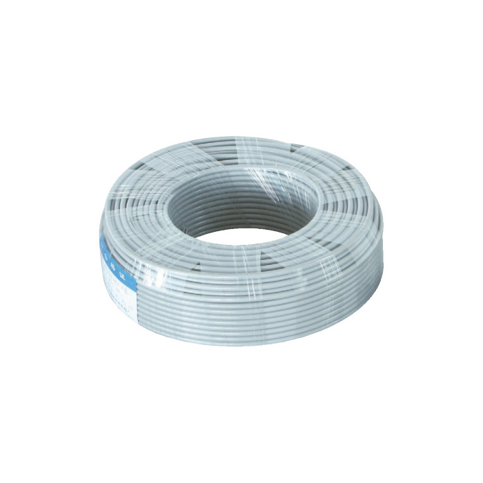
What a single shield does not establish
Shielding is part of the interference-control design, alongside cable routing, terminal connections and bonding. Its presence does not guarantee stable readings beside a variable-speed drive, nor does it correct a loose terminal or water-damaged connection. If readings change when a motor starts, record the timing and inspect the route before replacing the cable.
Where the installation specification calls for a sheathed double-shielded construction, review MV-WA0012. The alternative still needs a conductor specification and termination plan; shielding count alone is not a compatibility test.
Questions before extending a load-cell cable
Q1. Can spare cores simply be used to add remote sensing?
Only if the instrument and connection arrangement support the intended sense circuit. Extra conductors do not create a valid six-wire system on their own. Confirm where the sense voltage is measured and whether the proposed wiring is permitted by the sensor and instrument instructions.
Q2. Will the original calibration remain valid after an extension?
Do not assume it will. Changing the cable can change excitation losses and the connection arrangement. Check zero and response to known loads after installation; recalibrate when required by the instrument procedure and the results. Preserve the previous settings and test records for comparison.
Q3. Can this cable be specified for continuous flexing?
No continuous-flex rating is stated here. If the route moves with a machine, provide the motion, bend geometry and expected duty and obtain a suitable cable specification before purchase. A static cable photograph does not establish flex life.
Prepare a cable enquiry
Send the device models and terminal drawings, required installed length, conductor requirements, cable-entry sizes and route conditions with your MV-WA0011 enquiry. For an unstable existing system, attach photographs and a short record of when the reading changes. The cable shielding and grounding guide can help distinguish a cable fault from other causes.
