


 Chinese
 Spanish
 Russian
 Portuguese
 French
 German
 Indonesian
 Thai
 Vietnamese
 Arabic
 Italian
 Turkish
 Polish
 Japanese


A 120 GHz radar water level meter may be worth assessing for a narrow well, but frequency alone does not show that it will fit. The antenna needs usable distance at the highest water level, a sufficiently clear observation area at low water and a rigid, correctly oriented mount. A compact housing can still be unsuitable for the available measurement space.
Start with the Highest and Lowest Water Surfaces
At maximum water level, the surface is closest to the antenna. Compare that distance with the near-measurement limit for the exact ordered configuration, allowing for the actual antenna reference, mounting tolerances and the site's water movement. Raising a bracket may help clearance, but only if the opening and mounting arrangement remain suitable.
At minimum water level, the path is longest and the nominal beam footprint is largest. Check the whole path for well walls, ladders, cables, pipes, ledges and inlet structures. A narrow clear opening at the top does not prove that the lower part of the well is unobstructed.
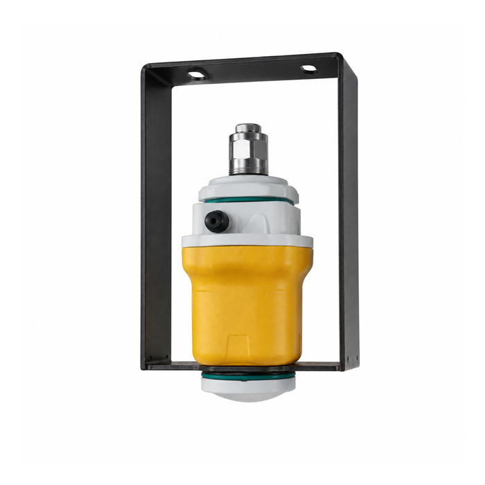
Estimate Clearance for a 120 GHz Radar Water Level Meter
For initial geometric planning, nominal beam diameter can be estimated as D = 2R tan(θ/2), where R is distance to the surface and θ is the specified full beam angle. Use the antenna data for the proposed configuration, not a typical angle associated with a frequency band.
For illustration only, a confirmed full angle of 5 degrees at a distance of 10 m gives a nominal diameter of about 0.87 m. A well with 0.80 m clear internal width would not provide full clearance for that centred nominal footprint. These example values are not a statement of the beam angle supplied with every MV-RD12T-120G.
A beam does not stop abruptly at that calculated diameter. Wall material, nearby reflectors, side responses and echo processing affect the actual installation. Use the calculation to identify a questionable arrangement, then assess the mounting details and verify echoes on site; do not treat it as a guaranteed detection boundary.
Alignment matters too. At 10 m vertical distance, a 1-degree tilt displaces the beam centre by approximately 0.17 m. That example shows why bracket adjustment and rigidity can be as important as the nominal beam width in a confined space. It is a geometry calculation, not an allowable installation tolerance.
Compare Configurations, Not Frequency Labels
The METRAVON MV-RD12T-120G uses 120 GHz radar with a PVDF antenna assembly for non-contact water level measurement. The MV-RD12T is an 80 GHz alternative. RS485 Modbus RTU configurations are available, but range, near limit, supply and output details must be confirmed for the selected version.
| Selection item | Ask for | Why it changes the decision |
|---|---|---|
| Near limit | The specified minimum measurement distance and its reference point. | A small housing does not guarantee measurement close to a high water surface. |
| Beam | The full-angle definition and installation guidance for the ordered antenna. | Clearance at low water depends on distance, alignment and obstacles. |
| Mount | Bracket dimensions, adjustment, cable clearance and access arrangement. | The sensor must remain aligned after installation and maintenance. |
| Interface | The selected supply, output version and matching communications document. | An available family option may not be included in the quoted unit. |
A higher operating frequency does not, on its own, establish a shorter blind zone, better installed accuracy or immunity to condensation. Compare the actual antenna and measurement configuration. Where two offers quote different limits, ask for a configuration-specific document before using either value in the installation drawing.
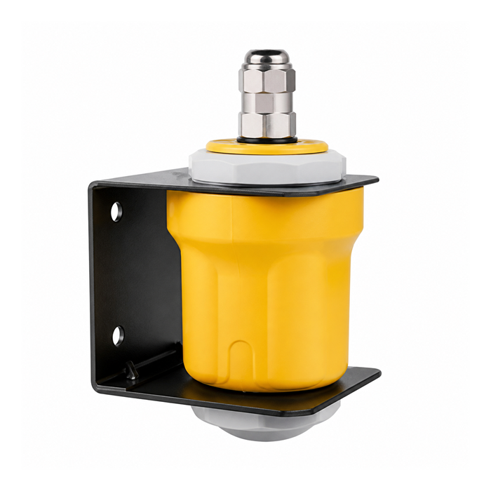
Check the Opening and Surface Conditions
A long sleeve or projecting edge can reflect energy before it reaches the water. Review the relationship between the antenna face and the roof opening, not just the flange or bracket bolt pattern. Do not assume that extending a pipe down a well creates a suitable radar installation; any proposed tube arrangement needs its own assessment.
Aim at a representative surface away from a falling inlet stream or a persistent local disturbance where the layout allows. Condensation and deposits require accessible inspection and an approved cleaning method. Neither frequency choice removes the need to manage these conditions.
Design routine maintenance from a safe access position. A well may be a confined space, and a level instrument does not change the site's entry controls. Where an inspection would require restricted access, include that burden when comparing mounting locations rather than discovering it after the cable is installed.
Prove the Reading Through the Operating Range
Record the initial instrument reference, orientation and configuration. Compare readings with an independent level observation at accessible operating points and review available echo diagnostics. Pay particular attention to the closest permitted surface and the lowest expected level, where the two different clearance problems occur.
If false-echo suppression is used, carry it out under the manufacturer's procedure with the real water level known. Suppressing an unidentified return can hide the water surface instead of removing an obstruction. Retain the settings and repeat the relevant checks after a bracket adjustment or sensor replacement.
Verify the receiving controller's units, update behaviour and invalid-data response. A stable but incorrect echo can look more convincing than a visibly noisy reading, so acceptance must include a reference comparison rather than a screen-stability judgement alone.
Questions About Narrow-Well Installations
Q1. Will changing from 80 GHz to 120 GHz solve wall echoes?
Not necessarily. It may help if the selected antenna provides a more suitable beam, but the result also depends on alignment, opening geometry and reflective objects. First identify where the unwanted return originates. Moving or correcting the mount can be more relevant than changing the frequency.
Q2. Can catalogue range be used as the installation acceptance limit?
Catalogue range describes an instrument capability under its stated conditions. It does not prove clear measurement through a particular well. Agree acceptance using the supplied configuration, actual high and low water positions, and independent checks at the site.
Q3. What drawing is needed before ordering?
Provide a vertical section with the antenna reference, opening dimensions, well width at each restriction, high and low water surfaces, and the locations of pipes or ladders. Add photographs and controller details. This is more useful than a single overall depth or a request for the highest available frequency.
Summary
Choose a narrow-well radar by checking near-surface distance, the complete sensing path and a maintainable mounting arrangement. Send the well section for an MV-RD12T-120G suitability review. A frequency-based shortlist becomes an orderable configuration only when those installation conditions and the required interface have been confirmed.
