


 Chinese
 Spanish
 Russian
 Portuguese
 French
 German
 Indonesian
 Thai
 Vietnamese
 Arabic
 Italian
 Turkish
 Polish
 Japanese


Radar level range setup must use one documented measurement reference. Tank height, empty distance, usable minimum and output span are different quantities. Copying the same number into several fields can produce a plausible percentage while moving the reported zero or reversing the trend seen by the PLC.
Draw the Reference Before Entering Parameters
Locate the antenna's measurement reference plane on the drawing for the exact instrument. Do not assume it is the housing base, lens tip or top of an adaptor. Measure from that plane to the chosen level-zero datum and record any nozzle or mounting offset.
The METRAVON MV-RD13 has different range and connection configurations. Its nominal 30 m or 150 m range describes an instrument option, not the height that should automatically be entered as the vessel's empty distance. Use the installed assembly and the actual required measuring interval.
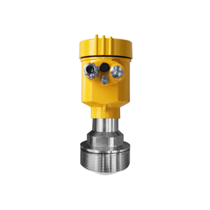
Radar Level Range Setup: Keep the Four Quantities Separate
| Quantity | Definition | Common mistake |
|---|---|---|
| Distance | Separation between the specified radar reference and the detected surface. | Interpreting decreasing distance as falling liquid level. |
| Empty distance | Configured separation from that reference to the selected zero datum. | Using an unverified vessel height from another drawing. |
| Usable minimum | The lowest process level that remains useful for the operating task. | Equating the pumpable limit with the physical tank bottom. |
| Output span | Difference between the selected lower and upper output values. | Assuming the output must cover the entire instrument range. |
For a vertical downward measurement with a common datum, level equals empty distance minus measured distance. That relationship is a geometry check, not permission to ignore the transmitter's own definitions. Confirm which variable the selected configuration sends to the receiving system.
Match the Transmitter and Receiver Without Applying the Conversion Twice
For a linear level output, record the level assigned to 4 mA and to 20 mA. Use those endpoints in the PLC scale. If the output is instead configured as distance, account for its direction and convert to level only where that conversion is intended.
Do not turn a percentage into volume by assuming every tank has a constant cross-section. First establish that the level value is correct. Apply a verified tank relationship separately and identify its datum. The tank-volume conversion guide explains why geometry changes the result.
Keep the highest operating surface outside the documented near-field limit, with the required process allowance for waves, foam or delayed inflow. Raising the configured span does not create reliable measurement closer to the antenna.
Use the Pattern of the Error to Choose the Next Check
A similar difference at several independently known levels suggests a reference or fixed-offset issue, although the reference method must also be checked. A difference that grows with level calls for a span or conversion review. Sudden jumps at particular heights require an echo investigation rather than a blanket correction.
Record raw distance, local level, actual output and PLC value at each test position. Comparing only the final percentage conceals where the mismatch begins. Use safe, approved reference methods; an inaccessible point should remain an unverified condition, not a fabricated acceptance result.
Range-Setting Questions
Q1. Can zero be set at the minimum useful liquid level?
It can be part of an explicitly defined operating display, but the resulting value must not be mistaken for height above the physical bottom. Keep inventory conversion and other alarms consistent with their own agreed datum. Document the relationship so maintenance does not later reset it unintentionally.
Q2. Is a one-point offset adjustment enough after replacement?
Only a justified constant difference can be addressed that way, and more than one point is needed to distinguish it from a span problem. Compare the new reference position, output assignment and receiver settings before making the adjustment.
Q3. What should be saved for future maintenance?
Retain the marked-up vessel section, measured reference distance, transmitter parameter file, output endpoints and PLC conversion. Add the comparison results and any untested operating limits. Those records make a later replacement repeatable instead of dependent on remembered settings.
Summary
A correct range setup connects a physical datum to an unambiguous output value. Request a range review with the installed drawing and transmitter-to-PLC scaling. Resolve the origin of any mismatch before applying an offset or changing the vessel calculation.
