


 Chinese
 Spanish
 Russian
 Portuguese
 French
 German
 Indonesian
 Thai
 Vietnamese
 Arabic
 Italian
 Turkish
 Polish
 Japanese


Channel geometry for radar flow measurement must describe the wetted section that actually exists. Construction drawings are a starting point, but sediment, lining changes and erosion can alter the area used in the discharge calculation. A correct radar distance cannot compensate for an obsolete section profile.
Channel Geometry for Radar Flow Measurement: Use a Common Datum
Survey the measurement section and relate the bed, staff gauge and radar reference plane to a documented elevation datum. Identify the distance reference specified for the instrument; do not assume that the housing top or bracket face is that reference. Keep measured distance and derived water level as separate recorded quantities.
For a vertical distance measurement, water-surface elevation follows from the reference-plane elevation minus the measured distance. Depth h is then the water-surface elevation minus the relevant bed elevation. An inclined installation requires the manufacturer's applicable geometric treatment rather than applying this vertical relation blindly.
Choose an Area Model That Matches the Section
| Section | Area model | Survey check |
|---|---|---|
| Rectangle | A = b × h, where b is the wetted channel width. | Confirm straight sides and a representative bed across the width. |
| Trapezoid | A = b × h + z × h squared for equal side slopes z horizontal to 1 vertical. | Measure bottom width b and both side slopes; the equation assumes they match. |
| Irregular | Use surveyed points to derive a stage-area table or equivalent section calculation. | Include changes of slope, benches and the highest surveyed water elevation. |
Use consistent units: metres for dimensions produce square metres for area. Test the configured calculation against independent geometry calculations at several surveyed elevations, including changes of slope. Define what happens above the surveyed range; overbank water cannot be represented by indefinitely extending the in-bank profile.
Check Where the Calculation Is Performed
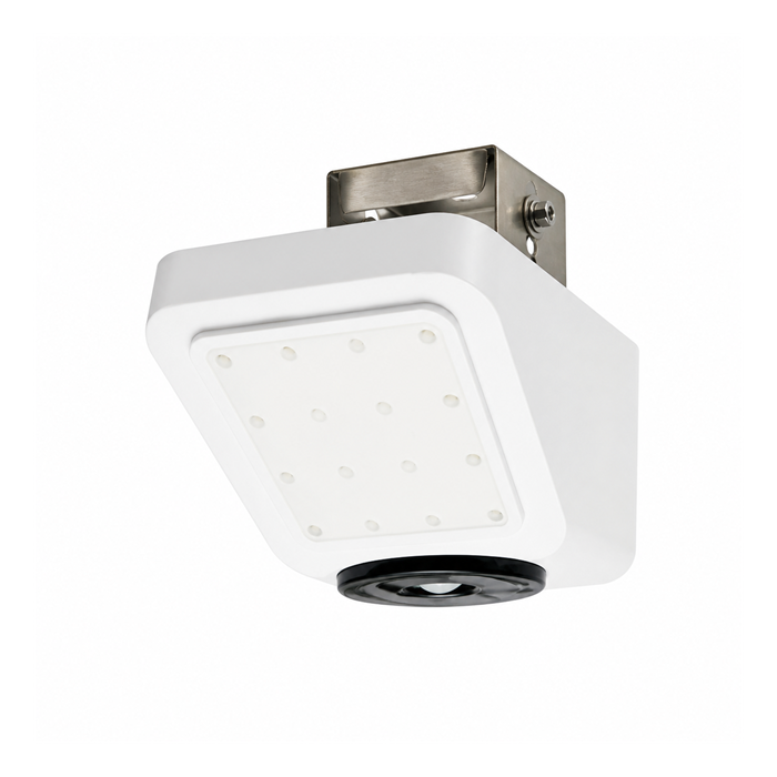
The METRAVON MV-RD2480 combines surface-velocity and level measurement with RS485 Modbus RTU communication. Confirm whether the approved geometry model is implemented in the supplied instrument configuration or in the RTU or data logger. Do not assume every device accepts arbitrary surveyed cross-sections.
Record the location of the velocity observation relative to the surveyed section. Surface velocity still requires a validated conversion to section mean velocity before using Q = A × Vmean. A correct area test alone is not a discharge calibration.
Maintain the Survey as Part of the Instrument Record
Keep the survey date, reference marks, raw points, implemented area table and effective revision date together. Inspect after dredging, flooding or construction, and when deposits or vegetation visibly change the section. Do not adjust the sensor zero simply to hide a bed change: the radar reference may still be correct while the wetted-area model has changed.
When the effect on historical data is uncertain, identify the affected period and its quality status. Reprocessing requires a defensible geometry history; the present survey does not prove exactly when a deposit formed.
Survey Questions
Q1. Is checking the level against a staff gauge enough?
It checks the water-level reference if both readings use the same datum. It does not verify the full cross-section, area algorithm or velocity conversion. Treat those as separate acceptance checks.
Q2. What should the survey package contain for a quotation?
Provide a dimensioned section with elevation reference, expected minimum and maximum water levels, mounting location, photographs and known changes such as sediment accumulation. Identify the proposed logger and whether an existing area table must be retained or replaced.
Summary
Approve the surveyed profile, reference elevations and implemented calculation together. Include these records in the radar flow-system enquiry so geometry processing and later maintenance are included in the supply scope.
