


 Chinese
 Spanish
 Russian
 Portuguese
 French
 German
 Indonesian
 Thai
 Vietnamese
 Arabic
 Italian
 Turkish
 Polish
 Japanese


An FMCW radar level meter estimates distance from a swept microwave signal and its delayed reflection. The level shown to an operator is a later calculation. Understanding that distinction helps decide whether a fault belongs to echo measurement, vessel reference settings or the receiving control system.
How an FMCW Radar Level Meter Obtains Distance
During a linear frequency sweep, the transmitted frequency changes at a known rate. The returning signal was transmitted earlier, so mixing it with the current transmitted signal produces a difference, or beat, frequency. For an ideal stationary target, distance R = c fb/(2S), where c is propagation speed, fb is beat frequency and S is sweep slope in frequency per unit time.
This simplified relationship explains ranging, not the complete firmware of a METRAVON instrument. Calibration, antenna behaviour and target processing also matter. The carrier-frequency label, such as 80 GHz, is not the sweep bandwidth, a distance-accuracy specification or an instruction to change internal radio parameters.
Follow the Result Through Four Stages
| Stage | Result | Question when wrong |
|---|---|---|
| Echo processing | Returns associated with candidate distances. | Is the wanted surface visible among the competing reflections? |
| Target selection | The distance used for measurement. | Does that target move consistently with the actual material? |
| Level conversion | Height relative to the configured vessel datum. | Does the empty-distance reference match the as-built position? |
| Transmission | A specified analogue or digital variable. | Does the receiver use the same variable, units and validity state? |
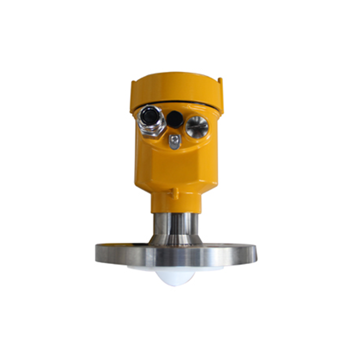
The METRAVON MV-RD12 is an 80 GHz liquid radar with a listed 32 mm PTFE lens and 8-degree beam. Those antenna properties affect placement. The quoted measuring range still needs to be checked against nozzle geometry, the closest surface and the actual process conditions.
Why a Correct Formula Can Still Produce the Wrong Process Value
A metal internal can produce a return at a real, repeatable distance without being the liquid surface. The problem is target identity, not necessarily a ranging error. Compare diagnostic peaks with vessel geometry and a known surface position before altering offsets.
Conversely, a correct surface distance can be converted with an incorrect zero reference or interpreted as the wrong variable by the PLC. Preserve distance and level together during checks. The range-setup procedure addresses that conversion separately.
Questions About the Measurement Principle
Q1. Is the beat frequency available as the PLC process value?
Do not assume it is exposed. Use the documented variables for the delivered interface. Commission the supplied distance or level output rather than requesting an undocumented internal signal.
Q2. Does FMCW identify every extra echo automatically?
The principle supports distance measurement, but installation and target selection still require validation. A difficult nozzle, deposit or unstable surface cannot be approved from the principle alone.
Q3. What distinguishes a measurement test from an output simulation?
A real-target test includes the antenna and surface interaction. Output simulation tests later electrical and software stages. Use each for its own purpose and keep their results separate in the acceptance record.
Summary
Trace errors to the stage where the value first becomes incorrect. Request an MV-RD12 application review with vessel geometry and the required receiver variable; specify how the installed measurement will be verified.
