


 Chinese
 Spanish
 Russian
 Portuguese
 French
 German
 Indonesian
 Thai
 Vietnamese
 Arabic
 Italian
 Turkish
 Polish
 Japanese


Guided wave radar probe buildup can alter the reflected signal, restrict liquid exchange or create a mechanical connection to nearby metalwork. Cleaning is useful only when it addresses the actual deposit and does not damage the probe. Preserve the as-found evidence before changing settings or removing material.
Guided Wave Radar Probe Buildup: Locate the Deposit First
| Location | Possible effect | Inspection focus |
|---|---|---|
| Upper probe | Adhering material or a bridge near the entry can create an unwanted reflection. | Nozzle deposits, clearance and the region above normal liquid level. |
| Probe length | A coating can change signal behaviour as its thickness or wetness changes. | Extent, adhesion and relationship to recent process cycles. |
| Coaxial tube | Blocked openings can delay exchange between the tube and vessel. | Openings, internal deposits and whether the reading follows rising and falling level. |
| Nearby parts | Contact or a material bridge can change both loading and reflection. | Probe alignment, supports and evidence of movement or impact. |
These are diagnostic possibilities, not proof of the cause. Compare the local indication with the control-system value and a suitable level reference. Save available echo or diagnostic information, operating temperature and recent batch history. A controller scaling fault will not be cured by cleaning a probe.
Protect the Covering During Cleaning
The METRAVON MV-RD702 uses corrosion-resistant probe covering options identified as PFA or PTFE. A compatible covering is not permission to scrape it with a metal tool or apply any solvent. Check the offered assembly, seal materials and approved cleaning procedure before choosing chemicals, temperature or mechanical force.
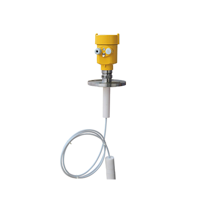
Isolate and make the process safe before removal. Photograph the deposit pattern where practical. Inspect for cuts, exposed metal, deformation and damaged terminations after cleaning. If a protective covering is damaged, obtain a repair or replacement decision rather than masking the resulting measurement error with an offset.
Use the Return to Service to Test the Diagnosis
Restore the approved installation and compare the cleaned instrument against the same reference used during diagnosis. Check both rising and falling level where the operating procedure allows it. For a coaxial arrangement, a satisfactory static point does not demonstrate that liquid exchange is fast enough during transfer.
Record how long acceptable performance lasts and under which recipes, temperatures or shutdown conditions deposits recur. That history supports a maintenance interval or a change of probe construction. An arbitrary monthly cleaning schedule can be excessive for one duty and inadequate for another.
Cleaning and Fault Questions
Q1. Can signal gain or false-echo settings compensate for crystallization?
They should not be the first response to an evolving deposit. Configuration changes can conceal a symptom while deposited material further restricts liquid exchange or increases probe loading. Establish the physical condition and follow the instrument-specific adjustment procedure only after assessing it.
Q2. When is changing the installation more useful than repeated cleaning?
When deposits return before the required service interval, access is unsafe or cleaning repeatedly damages the assembly, reconsider probe location, construction or measurement method. Support the decision with deposit photographs and operating records, not a promise that another frequency will eliminate fouling.
Summary
Diagnose the deposit location, clean within the assembly limits and verify dynamic response afterward. Send the probe identification, photographs and process history with a maintenance or replacement enquiry so the recommendation addresses the recurring cause.
