


 Chinese
 Spanish
 Russian
 Portuguese
 French
 German
 Indonesian
 Thai
 Vietnamese
 Arabic
 Italian
 Turkish
 Polish
 Japanese


Radar antenna selection should identify a complete process-facing assembly. A lens, horn or encapsulated design can change the space required, exposed materials and cleaning access. None of those names alone establishes beam angle, pressure suitability or resistance to the stored chemical.
Separate Antenna Geometry From the Material Barrier
A lens describes how the radiating assembly shapes the signal. A horn has a flared structure that must pass through the opening and remain clear. Encapsulation describes a covering or process barrier, so it is not necessarily an alternative to every lens or horn arrangement. Ask for a section drawing showing the actual construction.
For example, the METRAVON MV-RD12 uses a 32 mm PTFE lens with a listed 8-degree beam for liquids. Its lens material does not identify the flange metal or seal. Those parts need their own specification.
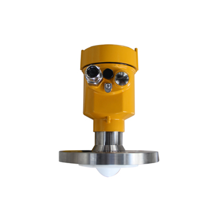
Radar Antenna Selection: What to Put on the Drawing
| Item | Record | Why it matters |
|---|---|---|
| Aperture | Actual diameter and the listed beam angle. | A family frequency does not define the footprint of every antenna. |
| Position | Antenna projection, nozzle bore, length and reducers. | A suitable antenna can still be screened by the installed nozzle. |
| Exposure | Process-facing materials and sealing surfaces. | Vapour and cleaning fluids may reach more than the visible antenna face. |
| Access | Withdrawal route and approved cleaning method. | Deposits must be inspectable without damaging the assembly. |
Compare Alternatives Within the Same Application
For a liquid vessel needing a narrower path, MV-RD13 lists a 76 mm PTFE lens and 3-degree beam. It also needs a different mounting review. Do not choose it only because its angle is smaller: the selected path must reach a useful surface through the complete operating range.
For solids, the MV-RD903 horn configurations have different diameters and beam angles. They belong in a silo comparison, not a claim that any horn can replace a liquid lens. Document the medium and measurement duty alongside each candidate.
Include the Deposit Mechanism in Acceptance
Describe whether the antenna encounters droplets, sticky films, crystals or abrasive material. A smooth face may offer fewer collection points, but it does not prevent every deposit. Inspect after a representative operating cycle and compare diagnostic returns before and after approved cleaning.
Do not add purge equipment merely because space exists for a fitting. The offered assembly, gas, process cleanliness and pressure boundary must support that arrangement. If no approved purge construction is available, select a maintainable mounting position or reconsider the instrument.
Antenna Questions
Q1. Does a larger aperture always improve the installation?
It can change beam characteristics, but may not fit the nozzle or maintenance route. Use the quoted antenna data and installed drawing rather than ranking alternatives by diameter alone.
Q2. What prevents a different antenna being supplied after review?
Put antenna type, dimensions, materials, connection and option code in the approved order. Receiving inspection should compare that assembly with the drawing, not just check the family name on the carton.
Summary
Choose an antenna that can be mounted, cleaned and verified in its actual duty. Request an antenna review with the nozzle section and deposit conditions, and retain the agreed construction in the purchase specification.
