


 Chinese
 Spanish
 Russian
 Portuguese
 French
 German
 Indonesian
 Thai
 Vietnamese
 Arabic
 Italian
 Turkish
 Polish
 Japanese



METRAVON MV-LC0190 is a miniature S-type load cell for low-force tensile fixtures and hanging-scale applications, with 1, 5, 20 and 50 kg choices. The 1 kg version has a different nominal sensitivity from the other three ratings. Its aluminum-alloy body and 0.2 m standard lead suit a close-coupled installation only when the mounting and nearby electrical connection are planned together.
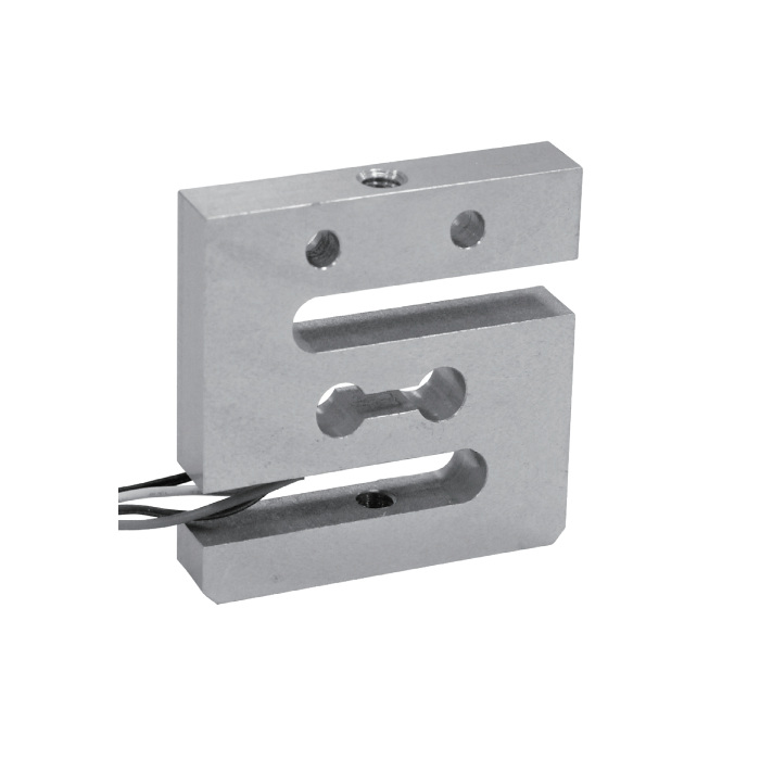
Use the selected capacity, not the overload limit, for normal measurement
Choose the rated load from the maximum force that can occur in the real fixture, including preload, test peaks and handling. The published safe overload is 120% F.S. and the ultimate overload is 150% F.S.; these are protection references, not additional measuring range. Low-capacity sensors are easily affected by cable pull, fixture weight and off-axis force, so those loads must be included in the setup review.
The 1 kg version has a different nominal sensitivity from the 5-50 kg versions. A replacement or multi-channel test bench must therefore be configured from the exact capacity on the nameplate rather than from the model family alone.
A capacity marked in kg is a nominal mass-equivalent rating, while a test machine may report newtons. Define that conversion in the calibration record. The fixture weight and preload still consume capacity after the display has been tared to zero.
Miniature S-type load cell reference data
Fixture design controls repeatability
Apply force through the intended mounting features and keep both attachments coaxial. A rigid connection that is slightly offset can bend the sensor and change the zero or span. Where the surrounding mechanism cannot maintain alignment, use an appropriate joint or linkage rather than forcing the load cell body to correct the geometry.
Prevent the cable from carrying load or rubbing against a moving part. The standard 0.2 m cable makes cable routing an early design decision. Do not shorten, extend or replace the cable without considering the signal conditioner, shielding and the calibration record.
Confirm the required force direction
Confirm that the selected sensor configuration and attachments are suitable for both directions before specifying a push-pull test. For an approved bidirectional setup, define the positive direction and verify the complete fixture separately in tension and compression. A one-direction calibration does not establish the response in the other direction; preload, joint clearance and backlash can change the zero crossing.
For a simple hanging-force application, include hook, shackle and fixture mass in the zero or tare procedure. For a test machine, record the force direction, crosshead position, loading rate and reference standard so later results can be compared under the same conditions.
Signal conditioning and data acquisition
The sensor output is not 4-20 mA or RS485. Use a bridge amplifier, indicator or data-acquisition input that supplies regulated excitation and accepts the expected mV/V signal. Check input noise and resolution at the lowest force of interest; a high display count does not compensate for electrical noise or mechanical friction.
When the result must reach a PLC, select a transmitter with the required 4-20 mA or digital output and calibrate the transmitter together with the sensor. For laboratory acquisition, preserve the raw bridge calibration and the engineering-unit conversion in the test record.
With 10 V excitation, the nominal full-scale signal change is 5 mV for the 1 kg version and 10 mV for the 5, 20 and 50 kg versions. These values are calculated from the listed sensitivities; zero offset and sensitivity tolerance also need input headroom. Use them to check amplifier range, then calibrate with known loads. For the steps between the bridge and the receiving controller, refer to load cell wiring and PLC integration.
A practical acceptance check
- Inspect the sensor, cable and mounting faces before assembly.
- Install the unloaded fixture and record zero after the specified warm-up period.
- Apply traceable loads in increasing steps without side contact or cable pull.
- Unload in steps and record return to zero; repeat the sequence to assess repeatability.
- For bidirectional use, repeat with compression and document the sign convention.
- Verify the value at the final display, PLC or data-acquisition channel.
Common purchasing questions
Q1. Which capacity should be used for a 4 kg test?
The 5 kg version may be a starting point only if fixture weight, preload and peak force remain within its working range. If impact or overshoot can exceed the rating, change the mechanical test method or select a higher capacity after considering the required resolution.
Q2. Does +/-0.2% F.S. mean 0.2% of the displayed reading?
No. F.S. refers to the selected sensor's full-scale capacity. For example, 0.2% of a 5 kg range is a 10 g mass equivalent; it is not 0.2% of every smaller load. This calculation is neither a resolution specification nor a guarantee for the complete fixture. Include amplifier noise, reference-load uncertainty, friction and repeatability in the test-system assessment.
Q3. Is IP65 suitable for outdoor or washdown use?
IP65 is a product reference, not approval for immersion or repeated high-pressure washing. Review enclosure exposure, cable termination, corrosion and drainage for the complete installation.
Q4. Why does the zero move when the cable is repositioned?
At low forces, cable stiffness can transfer a measurable load into the fixture. Secure the cable to the stationary structure with enough slack for the required movement, then repeat the unloaded check. If the reading remains unstable without mechanical disturbance, investigate connections, excitation and electrical noise before recalibrating.
Send the fixture drawing and force range
Request an MV-LC0190 quotation with the minimum and maximum test forces, loading direction, fixture weight, mounting drawing and available amplifier. Include cyclic loading, expected overshoot, temperature and cable routing. If the required capacity or mounting arrangement falls outside this model, compare the other METRAVON load cell structures before adapting the fixture.
