


 Chinese
 Spanish
 Russian
 Portuguese
 French
 German
 Indonesian
 Thai
 Vietnamese
 Arabic
 Italian
 Turkish
 Polish
 Japanese



METRAVON MV-LC0155 is a threaded beam load cell with a side cover, listed for platform, pallet and weighing-module applications. It offers 250 and 500 kg plus 1, 1.5, 2, 2.5, 3, 5, 7.5 and 10 t. Confirm the capacity and exact load-end thread together; retaining a similar-looking foot can leave a pitch or height mismatch unresolved.
Keep the threaded beam load cell and weighing foot on the same drawing
The lower dimensional group uses M12 x 1.75 with a 130 mm body length and 31.8 mm height. At 3 and 5 t the values change to M20 x 1.5, 171.5 mm length and 38.1 mm height; at 7.5-10 t they are M24 x 2, 222.3 mm and 50.8 mm. Check the mating foot, engagement and installed support height before ordering. An M12 description without pitch is not a complete match to the lower-group connection.
| Item | Value | Selection notes |
|---|---|---|
| kg capacities | 250, 500 kg | A dimensional row starting at 100 kg does not add that rating. |
| t capacities | 1, 1.5, 2, 2.5, 3, 5, 7.5, 10 t | Keep each load rating with its matching dimensional group. |
| Lower-group loading thread | M12 x 1.75 | Compare the complete thread, not its diameter alone. |
| 3-5 t loading thread | M20 x 1.5 | Review the longer body and larger fixing pitch. |
| 7.5-10 t loading thread | M24 x 2 | The corresponding body height is 50.8 mm. |
| Excitation | 4-12 V DC; maximum 15 V DC | Confirm reader input and shared excitation capacity. |
| Working temperature | -30 to +70 deg C | Assess the completed cable termination and local exposure. |
Check the base pitch and supported part of the beam
Fixing pitch is 25.4 mm in the lower group, 38.1 mm at 3-5 t and 50.8 mm at 7.5-10 t. The drawing locates the measuring and fixing features relative to the loading point; use it to review an adapter, not merely to copy two hole centres. Keep unwanted contact away from the sensing section. The side cover does not document a field adjustment or repair procedure, so resolve any service requirement before opening or modifying the sensor.
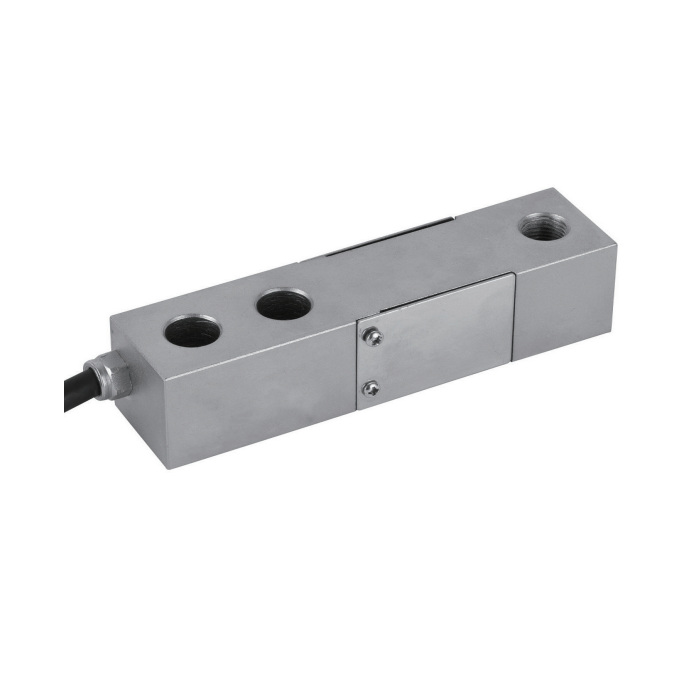
Resolve the 250 kg and 3 t cable entries on the offer
The cable note gives 3 m for 500 kg-3 t and 6 m for 3-10 t, leaving the 3 t boundary in both groups and not identifying the 250 kg length. Request the delivered lead length and termination for those orders instead of choosing a convenient group. The listed cable is four-core with 5 mm diameter. Rated sensitivity is 2.0 +/-0.002 mV/V, with 385 +/-10 ohms input resistance and 351 +/-2 ohms output resistance.
Agree the installed verification before restoring the scale
Record the original support arrangement, tare, greatest individual reaction and reader settings before replacing parts. After the new beam and final load attachment are secure, set zero and span using agreed references. Check repeat readings, load position response and unloaded return rather than accepting a plausible display value alone. The published 30-minute creep is +/-0.02% FS. Confirm required system performance and any approval documents independently of the C3 class entry.
Capacity boundaries and the 3 t lead
Q1. Does the 100 kg dimensional-row boundary establish a 100 kg sensor?
The capacity list starts at 250 kg. Do not use a broader dimensional-group label to add an undocumented capacity. Request a confirmed alternative if the required rating is below 250 kg.
Q2. Should a 3 t order specify 3 m or 6 m of cable?
Both cable groups include 3 t, so the model note does not resolve the delivered length. State the required route and termination and obtain the accepted length on the quotation. Set the final calibration after that cable arrangement is installed.
